321037
50
11.4.4
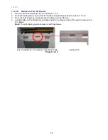
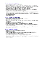
Removal of PC Fan Motor
1. Unplug the refrigerator from the outlet socket.
2. Remove all the PC shelving and trays.
3. Unclip the PC air duct cover but do not remove.
4. Remove the polystyrene duct cover insulation.
5. Turn the PC cover to expose the back of the cover.
6. Remove the PC sensor from the cover and remove the cover.
7. Remove the duct grill and polystyrene insulation.
8. Using 2 fingers, withdraw the fan motor upwards. It is mounted horizontally in the divider
partition.
9. With the motor out, this will expose a small multi plug and socket connection to the fan motor
and wiring harness. Unplug.
10. To refit back together, connect the multi plug, then fit the wiring harness multi plug into the
pocket of the divider partition.
11. Using 2 fingers, slip the motor back into the divider partition to fit horizontally and locate the
lugs into the retainers. The routing of the wiring is important.
Note:
The back of the fan motor faces upwards.
12. Refit the duct covers and test.
The fan is fitted with an over moulded suspension. Before fitting, check the suspension legs to
ensure the legs are not loose or broken.
11.4.5
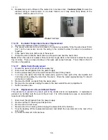
Replacing Cross / Base Rail Reed Switches
1. Unplug the refrigerator from the outlet socket.
2. Remove the reed switch cover by placing a small bladed screwdriver into the slot under the
cover and lifting off.
3. Unclip the encapsulated reed switch from the housing.
4. Cut off the wiring to the reed switch as close to the switch as possible.
5. Replacement of the new reed switch is done by cutting the wire off the new reed switch about
60mm (2.4”) from the reed switch, stripping the wire back about 10mm (0.4”), stripping the old
reed switch wiring back about 10mm (0.4”), and after sliding heat shrink onto the wires,
soldering the new reed switch to the old wiring, making sure both connecting wires are not
shorting but are insulated with heat shrink sleeving. Take care not to leave too much excess
wire, as the read switch must be able to be fitted back into the housing.
6. Refit in reverse order.
11.4.6
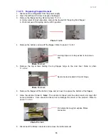
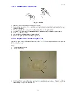
Removal of the drawer slide panels
The drawer slide side panels are held in place by the means of a dovetail mould in the cabinet
liner. To remove both left and right hand panels.
1.
First remove the screw that holds the back edge of the side panel to the liner panel.
2.
Flex the top edge of the panel out to release the locking tab and plull the panel forward
3.
Disengaging the panel from the dove tail
4.
Refit in reverse order.
Summary of Contents for RF175W
Page 1: ...321037 Service Manual Active Smart Refrigerator Freezer Models RF195A RF175W...
Page 19: ...321037 19 5 4 5 Condenser Mullion Layout Diagram 5 4 5...
Page 77: ...321037 77 15 WIRING DIAGRAM 15 1 RF175 Wiring Diagram...
Page 78: ...321037 78 15 2 RF175 Control Module Wiring Diagram...
Page 79: ...321037 79 15 3 RF175 Ice Water Wiring Diagram...
Page 80: ...321037 80 15 4 RF175 Ice Water Control Module Wiring Diagram...
Page 81: ...321037 81 15 5 RF195A Ice Water Wiring Diagram...
Page 82: ...321037 82 15 6 RF195A Ice Water Control Module Wiring Diagram...

