321037
67
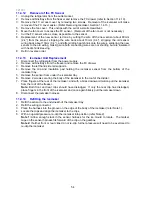
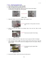
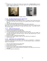
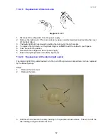
Note: Before any testing is carried out, ensure the product has an ice bin in place and the icemaker
arm is in the down position.
Procedure:
•
Disconnect the refrigerator from the power supply.
•
Remove the power module to expose connectors.
•
Remove the connector from the Icemaker PCB.
•
Check the resistance of the motor between pins 5 & 6 - resistance should be 35
Ω
+/- 5%.
•
Check the tact switch continuity between pins 4 & 7 - the switch should be closed.
Note: To identify pin numbering, Pin 10 and 11 are white wires
An alternative method of testing the icemaker unit is to use a 9-volt battery plus battery terminal
and a multi meter. With the meter probes placed into the back of the icemaker 4 way socket onto
the yellow and blue wires, check the continuity of the circuit to the tact switch in the ice mould tray.
The switch should be closed.
By applying a 9 volt DC supply across the white and red wires of the plug to the icemaker motor,
you can drive the ice mould tray forward to a full twist of the tray and the tact switch will close
again.
Note:
•
9-volt battery positive to the red wire to go forward.
•
9-volt battery positive to the white wire to go backwards.
Checking the tact switch
Advancing the motor
Pins 10 & 11
Motor - Pins 5 & 6
Tact switch continuity –
Pins 4 & 7
Summary of Contents for RF175W
Page 1: ...321037 Service Manual Active Smart Refrigerator Freezer Models RF195A RF175W...
Page 19: ...321037 19 5 4 5 Condenser Mullion Layout Diagram 5 4 5...
Page 77: ...321037 77 15 WIRING DIAGRAM 15 1 RF175 Wiring Diagram...
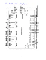
Page 78: ...321037 78 15 2 RF175 Control Module Wiring Diagram...
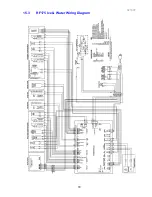
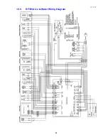
Page 79: ...321037 79 15 3 RF175 Ice Water Wiring Diagram...
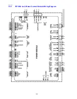
Page 80: ...321037 80 15 4 RF175 Ice Water Control Module Wiring Diagram...
Page 81: ...321037 81 15 5 RF195A Ice Water Wiring Diagram...
Page 82: ...321037 82 15 6 RF195A Ice Water Control Module Wiring Diagram...


