321037
56
9. Replacement and re-fitment of the element is in reverse order.
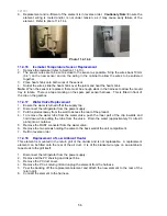
Cautionary Note:
Ensure the
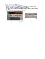
element wiring is routed and/or is not under tension, as it may cause early failure of the
element. Refer to photo 11.4.14.4
Photo 11.4.14.4
11.4.16
Icemaker Temperature Sensor Replacement
1. Remove the icemaker (refer to Section 11.4.13).
2. The sensor wires are to be cut as close to the sensor as possible. Strip the wires back 10mm
(0.4”) on the new sensor and on the wiring in the cabinet to allow the wires to be soldered
together.
3. Place heat shrink onto both wires of the sensor.
4. Solder the wires, slide the heat shrink over the joints and heat the heat shrink.
Note:
When the sensor is replaced, there must be enough slack in the harness to allow the mould
tray to rotate. There is a tape marking on the spare part sensor harness. This is fitted in front of
the clip on the gearbox.
11.4.17
Water Valve Replacement
1. Ensure the water is turned off at the supply tap.
2. Disconnect the refrigerator from the power supply.
3. Pull the product away from the wall to access the rear of the product.
4. To remove the water tube from the water valve, push the inner part of the clip inwards and
hold down while pulling the tube from the valve. Drain the water (approximately 1½ litres/3
pints) into a container.
5. Remove the RAST connector from the water valve.
6. Remove the two screws holding the valve to the back wall of the unit compartment.
7. Refit in reverse order.
11.4.18
Replacement of Low Ambient Heater
This element is mounted in the return grill of the divider and is not replaceable. A replacement
element can be fitted onto the rear of the air duct. It is of the blanket wire type on an aluminium
tape stuck to the grill itself.
1. Disconnect the refrigerator from the power supply.
2. Remove all the PC shelving and crisper bins.
3. Remove the PC duct cover.
4. Remove the PC air return grill and unplug the element from the harness.
5. Peel the backing off the replacement element and attach the new element to the rear of the
return grill.
6. Connect the element to the harness.
Summary of Contents for RF175W
Page 1: ...321037 Service Manual Active Smart Refrigerator Freezer Models RF195A RF175W...
Page 19: ...321037 19 5 4 5 Condenser Mullion Layout Diagram 5 4 5...
Page 77: ...321037 77 15 WIRING DIAGRAM 15 1 RF175 Wiring Diagram...
Page 78: ...321037 78 15 2 RF175 Control Module Wiring Diagram...
Page 79: ...321037 79 15 3 RF175 Ice Water Wiring Diagram...
Page 80: ...321037 80 15 4 RF175 Ice Water Control Module Wiring Diagram...
Page 81: ...321037 81 15 5 RF195A Ice Water Wiring Diagram...
Page 82: ...321037 82 15 6 RF195A Ice Water Control Module Wiring Diagram...


