321037
17
5.4 Servicing
Features
5.4.1 Condensate
Disposal
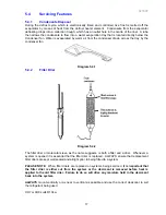
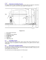
During the defrost cycle, which is electronically timed and controlled, live frost is melted off the
evaporator by means of heat from the defrost heater element. Condensate from the evaporator
defrosting drops into a collection trough, which has an outlet hole in the centre of the liner. A tube
then allows the condensate to flow into a water evaporation tray that is located directly below the
Condenser fan. Water is evaporated by warm air from the condenser drawn across the tray by the
condenser fan.
Diagram 5.4.1
5.4.2 Filter
Drier
Diagram 5.4.2
The filter drier or molecular sieve, as the name suggests, is both a filter and a drier. Whenever a
system is opened it is essential that the filter drier is replaced. ALWAYS ensure that replacement
filter driers are kept well sealed and airtight prior to being fitted to a system.
PLEASE NOTE
: When filter driers are replaced on systems being serviced,
it is important that
the filter drier is either cut from the system or the desiccant is removed before heat is
applied to the old filter drier. Failure to do so will drive any moisture held in the desiccant
back into the system.
ALWAYS
mount vertically or as near to vertical as possible and use the correct desiccant to suit
the refrigerant being used.
XH7 or XH9 suits R134a.
Summary of Contents for RF175W
Page 1: ...321037 Service Manual Active Smart Refrigerator Freezer Models RF195A RF175W...
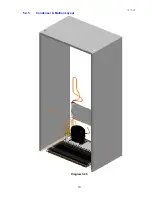
Page 19: ...321037 19 5 4 5 Condenser Mullion Layout Diagram 5 4 5...
Page 77: ...321037 77 15 WIRING DIAGRAM 15 1 RF175 Wiring Diagram...
Page 78: ...321037 78 15 2 RF175 Control Module Wiring Diagram...
Page 79: ...321037 79 15 3 RF175 Ice Water Wiring Diagram...
Page 80: ...321037 80 15 4 RF175 Ice Water Control Module Wiring Diagram...
Page 81: ...321037 81 15 5 RF195A Ice Water Wiring Diagram...
Page 82: ...321037 82 15 6 RF195A Ice Water Control Module Wiring Diagram...


