321037
43
To exit the diagnostic mode, press the
MENU
key. If not terminated manually, the diagnostic mode
will time out and go back to default display after 5 minutes.
Note: The door alarms do not operate when the appliance is in diagnostic mode.
9
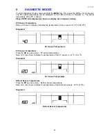
INPUT / OUTPUT STATUS
To enter input / output status:
•
Press and hold the
MENU
key, then press the
UP
key for 4 seconds. This enters the
Diagnostic mode.
•
Press
the
UP
key three times. The current input /output status will be displayed.
•
If a device is on or a door is open, the respective LCD will be on.
•
Return to normal operation by pressing the
MENU
key.
•
Note: Only the first 6 LCD’s are used. The last 5 are not used.
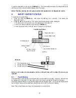
Input/Output Status
Example.
•
The Compressor is on.
•
The FC fan is on.
•
The PC fan is on.
Note: In I/O mode the illumination of the LCD will turn off if either PC doors are
opened.
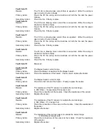
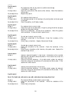
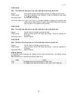
9.1 Fault
History
The Fault History will indicate the last fault that occurred with the product. However, this will only
be displayed for a periods of 4 days, after which it can only be accessed through a download.
It will also indicate if there are any further faults with the display board. If an icemaker display fault
has occurred, these will be indicated by fault codes F40 or F41 on the LCD Display.
Note: This is fault history and may not necessarily be a current fault.
Light on.
Low Ambient heater on.
Defrost heater
on.
FC fan on when
door is closed.
Compressor on.
PC Fan on.
Upper door open.
Lower drawer open
Summary of Contents for RF175W
Page 1: ...321037 Service Manual Active Smart Refrigerator Freezer Models RF195A RF175W...
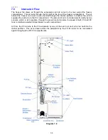
Page 19: ...321037 19 5 4 5 Condenser Mullion Layout Diagram 5 4 5...
Page 77: ...321037 77 15 WIRING DIAGRAM 15 1 RF175 Wiring Diagram...
Page 78: ...321037 78 15 2 RF175 Control Module Wiring Diagram...
Page 79: ...321037 79 15 3 RF175 Ice Water Wiring Diagram...
Page 80: ...321037 80 15 4 RF175 Ice Water Control Module Wiring Diagram...
Page 81: ...321037 81 15 5 RF195A Ice Water Wiring Diagram...
Page 82: ...321037 82 15 6 RF195A Ice Water Control Module Wiring Diagram...

