321037
14
5
THEORY OF OPERATION
5.1 Terms
CABINET WRAPPER
Pre-painted steel.
LINER
A two-piece vacuum formed HIPS liner.
DIVIDER
Is formed by the two-piece vacuum formed liners.
FAN MOTORS
DC 12 volt brushless variable speed fan motors for air circulation in both 1 x FC and 1 x PC
compartments.
CONDENSER
All wire on tube located in base tray.
CONDENSER FAN
The condenser fan is 110 volt and is connected in parallel with the compressor circuit.
EVAPORATOR
Aluminium Fin on Tube type mounted vertically on the back wall of the FC compartment.
SUCTION & CAPILLARY LINE
Foamed into the back of the cabinet with all joints to the evaporator brazed in the FC.
POWER / CONTROL MODULE
Contains the microprocessor that controls all functions of the refrigerator and gathers data from the
sensors. This module also contains support circuitry to switch the various outputs.
DISPLAY MODULE
Using signals from the Power Module, this module generates the LED display. The lamp is also
switched from this module.
REED SENSORS
Reed switches encapsulated within plastic housings are mounted on the cross and base rails
behind plastic covers. A magnet housed just under the lower end cap of each door activates these
reed switches when the doors are closed.
COMPARTMENTS
In this manual we refer to the refrigerator compartments as follows:
•
PC = Provision or fresh food compartment.
•
FC = Freezer compartment.
LOW AMBIENT HEATER
Blanket wire type attached to the base of the PC liner.
Summary of Contents for RF175W
Page 1: ...321037 Service Manual Active Smart Refrigerator Freezer Models RF195A RF175W...
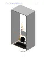
Page 19: ...321037 19 5 4 5 Condenser Mullion Layout Diagram 5 4 5...
Page 77: ...321037 77 15 WIRING DIAGRAM 15 1 RF175 Wiring Diagram...
Page 78: ...321037 78 15 2 RF175 Control Module Wiring Diagram...
Page 79: ...321037 79 15 3 RF175 Ice Water Wiring Diagram...
Page 80: ...321037 80 15 4 RF175 Ice Water Control Module Wiring Diagram...
Page 81: ...321037 81 15 5 RF195A Ice Water Wiring Diagram...
Page 82: ...321037 82 15 6 RF195A Ice Water Control Module Wiring Diagram...


