4150K and 4160K Series
20
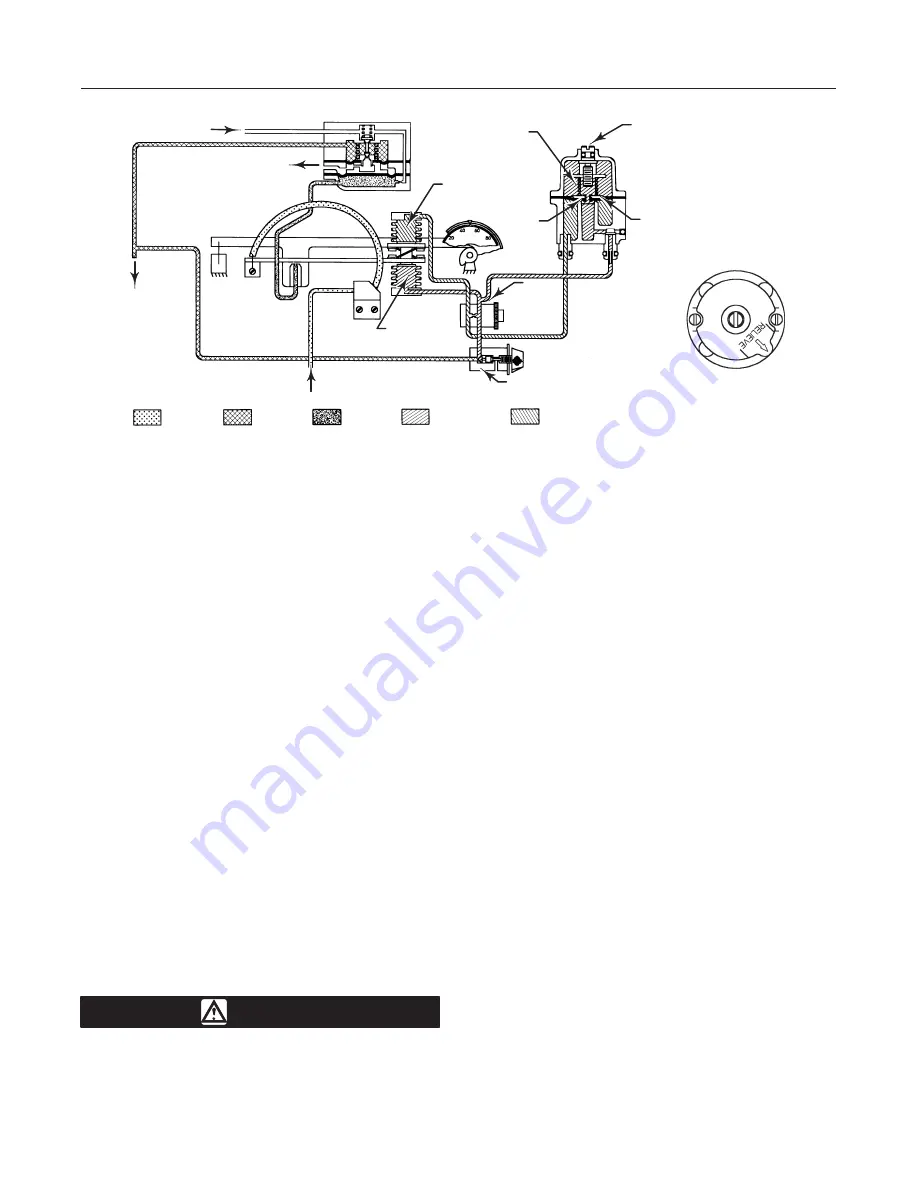
Figure 15. Schematic of Reverse-Acting Proportional-Plus-Reset
Controller with Anti-Reset Windup
CONSTANT SUPPLY
PRESSURE
TO FINAL
CONTROL
ELEMENT
EXHAUST
RESET
BELLOWS
ADJUSTING
SCREW
ORIFICE
RELIEF VALVE
DIAPHRAGM
WITH ARROW DOWN-
RELIEVES ON
DECREASING OUTPUT
(OUTPUT AT SUPPLY
DURING SHUTDOWN)
SENSED
PRESSURE
PROPORTIONAL
BELLOWS
RESET
VALVE
LOADING
PRESSURE
NOZZLE
PRESSURE
PROPORTIONAL
PRESSURE
RESET
PRESSURE
38B6006-C
B1562-5 / IL
SENSED
PRESSURE
RELIEF VALVE
SPRING
PROPORTIONAL
VALVE
Transmitters
Action of a pneumatic transmitter is similar to that of a
proportional-only controller. Since the output pressure
of the transmitter has no effect on the process pres-
sure, transmitter output pressure is a proportional
measure of the process pressure. The proportional
valve determines the span of the transmitter, and the
pressure setting mechanism determines the zero of
the transmitter.
Maintenance
If the installation includes a 67 Series filter regulator,
periodically open the drain on the filter regulator to
drain accumulated moisture. Also, push the cleaner
wire on the relay orifice (key 88, figure 23). Check the
opening of the vent assembly (key 15, figure 3) or the
opening of the remote vent pipe, if one is used. If nec-
essary, clean the openings.
Parts are subject to normal wear and must be in-
spected and replaced as necessary. The frequency of
inspection and parts replacement depends upon the
severity of the service conditions. Due to the care
Fisher takes in meeting all manufacturing require-
ments (dimensional tolerances, etc.), use only replace-
ment parts manufactured or furnished by Fisher.
WARNING
The following maintenance procedures
require taking the controller out of ser-
vice. To avoid personal injury and prop-
erty damage caused by the release of
pressure or process fluid, observe the
following before starting maintenance:
D
Provide some temporary means of
control for the process before taking the
controller out of service.
D
Provide a means of containing the
process fluid before removing any mea-
surement devices from the process.
Replacing Gauges
Refer to figures 19 and 20 for key number locations
unless otherwise directed.
Three gauge configurations are available for 4150K
and 4160K units.
D
Output and supply pressure indications
D
Output and process pressure indications
D
Output, process, and supply pressure indications
One gauge type (key 13) is used for both output and
supply pressure indications when the gauges are
installed inside the controller case. Key 13 features a
1/8-inch connecting stem that matches the threaded
gauge boss extending from the relay base.
In some cases, a process pressure gauge (key 106)
covers the position of the internal supply pressure
gauge. The supply pressure gauge has been removed
and replaced with a pipe plug (key 108). The pressure
control block (key 8) is different to accommodate a
different control tubing assembly (key 132) with a


