


4150K and 4160K Series
18
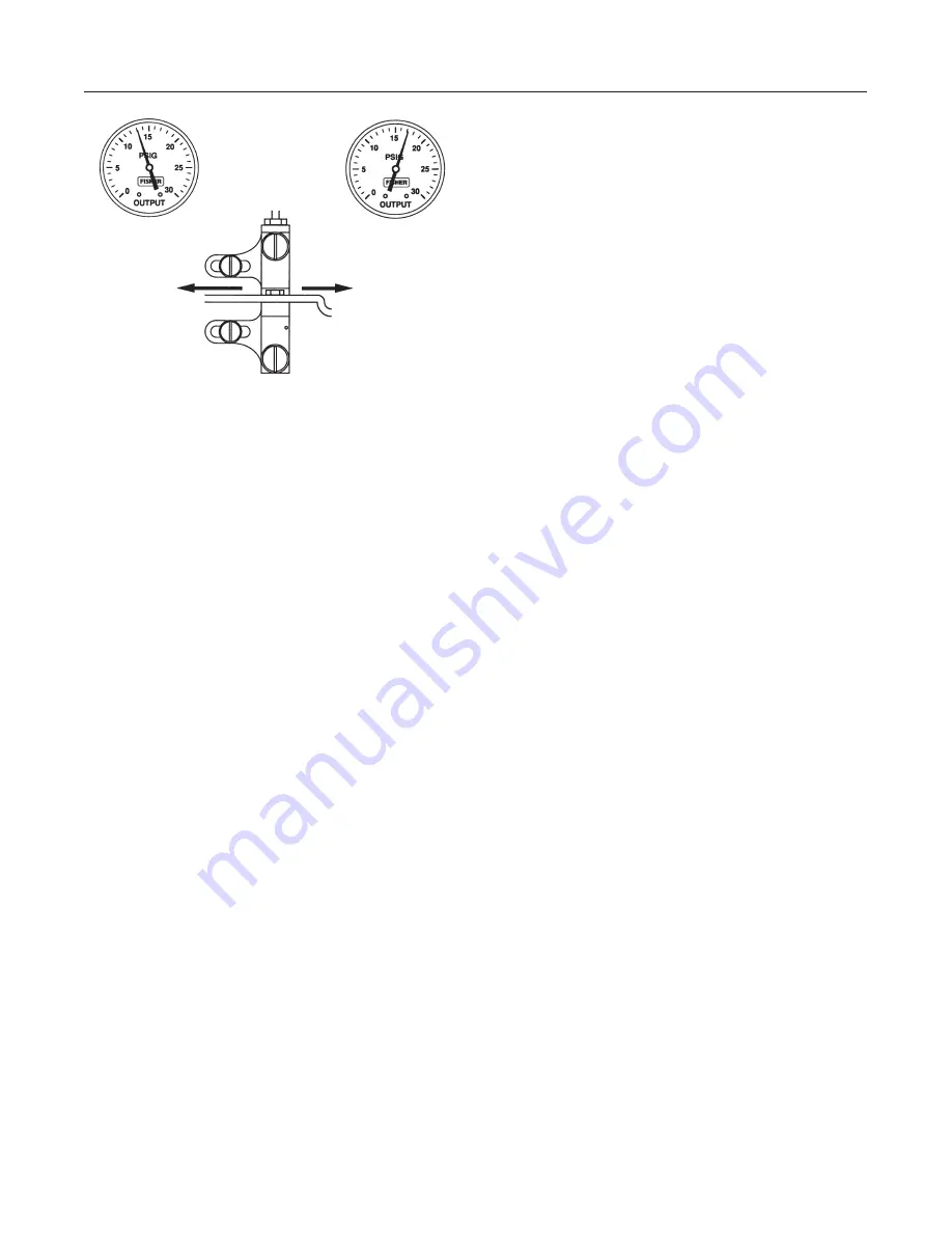
Figure 13. Transmitter Span Adjustment
IF OUTPUT IS:
MOVE ADJUSTER
LEFT
MOVE ADJUSTER
RIGHT
NOTE:
3 TO 15 PSIG (0.1 TO 1.0 BAR) OUTPUT SHOWN.
FOR 6 TO 30 PSIG (0.2 TO 2.0 BAR) OUTPUT, ADJUST
VALUES AS APPROPRIATE.
A6156 / IL
ABOVE
15 PSIG
(1.0 BAR)
BELOW
15 PSIG
(1.0 BAR)
from being misaligned with the flapper.
During calibration, always be sure the
nozzle remains perpendicular to the
flapper.
8. If the output pressure is not 15 psig, adjust the span
by loosening one of the two adjusting screws (key 43)
and move the calibration adjuster (key 41) a small dis-
tance as indicated in figure 13.
9. Repeat steps 4 through 8 until no further adjustment
is necessary.
10. Proceed to the startup procedure for transmitters.
Startup: Transmitters
1. Be sure that the supply pressure regulator is deliv-
ering the proper supply pressure to the transmitter.
2. Refer to the calibration procedures for the transmit-
ter initial settings.
3. If the transmitter is used in conjunction with a con-
trol valve, slowly open the upstream and downstream
manual shutoff valves, and close the bypass valves.
Principle of Operation
The following sections describe the operation of a con-
troller or transmitter using a Bourdon tube sensing ele-
ment. The operation is the same for an instrument us-
ing a bellows sensing element (key 71, figure 22)
except that movement of the beam is caused by ex-
pansion or contraction of the bellows or differential
bellows.
Proportional-Only Controllers
As shown in figure 14, supply pressure enters the
relay and bleeds through the fixed orifice before es-
caping through the nozzle. Nozzle pressure also regis-
ters on the large relay diaphragm, and loading pres-
sure (controller output pressure) registers on the small
relay diaphragm.
A change in the process pressure moves the beam
and flapper with respect to the nozzle by either ex-
panding or contracting the Bourdon tube arc. An in-
creasing process pressure with direct action (or de-
creasing pressure with reverse action) produces a
nozzle-flapper restriction that increases the loading on
the large relay diaphragm and opens the relay valve.
Additional supply pressure flows through the relay
chamber to increase the loading pressure on the con-
trol valve actuator. A decreasing process pressure
with direct action (or increasing pressure with reverse
action) produces a nozzle-flapper opening that bleeds
off pressure on the large relay diaphragm and opens
the relay valve to exhaust controller output pressure
from the actuator.
This controller output pressure change feeds back to
the proportional bellows, countering the pressure
change in the nozzle and equalizes the relay dia-
phragm pressure differential. The relay valve main-
tains a new loading pressure according to the change
in sensed pressure.
If the proportional valve is wide open, all of the control-
ler output pressure change feeds back to the propor-
tional bellows. The more the proportional valve is
closed, the more the controller output pressure change
bleeds out through the proportional valve exhaust and
the less there is to feed back to the proportional bel-
lows. A fully open proportional valve results in a pro-
portional band of 100 percent; closing the proportional
valve reduces the proportional band.
Proportional-Plus-Reset Controllers
Action of a proportional-plus-reset controller is similar
to that of a proportional-only controller except that
feedback from the controller output pressure is piped
to a reset bellows as well as to the proportional bel-
lows as shown at the right in figure 14.
With an increasing controller output pressure, pres-
sure in the reset bellows increases. Increases in reset
bellows pressure moves the beam and flapper closer
to the nozzle, starting another increase of pressure
throughout the system. Pressure buildup continues
until the controlled pressure is brought back to the set
point. The reset valve is adjustable to vary the amount
of delay in the reset action. Closing the reset valve
increases the delay in reset action.


