12
The two auxiliary inputs can be configured via option parameters to provide / override various status
inputs such as fault mute, burner on etc.
If the hand/auto (H/A) input is off, the UP and DN inputs will have no effect, and the unit will mod-
ulate automatically.
If the hand/auto (H/A) input is on, the UP input will cause the modulation rate to increase
if it is energized, and the DN input will cause the modulation rate to decrease if it is
energized.
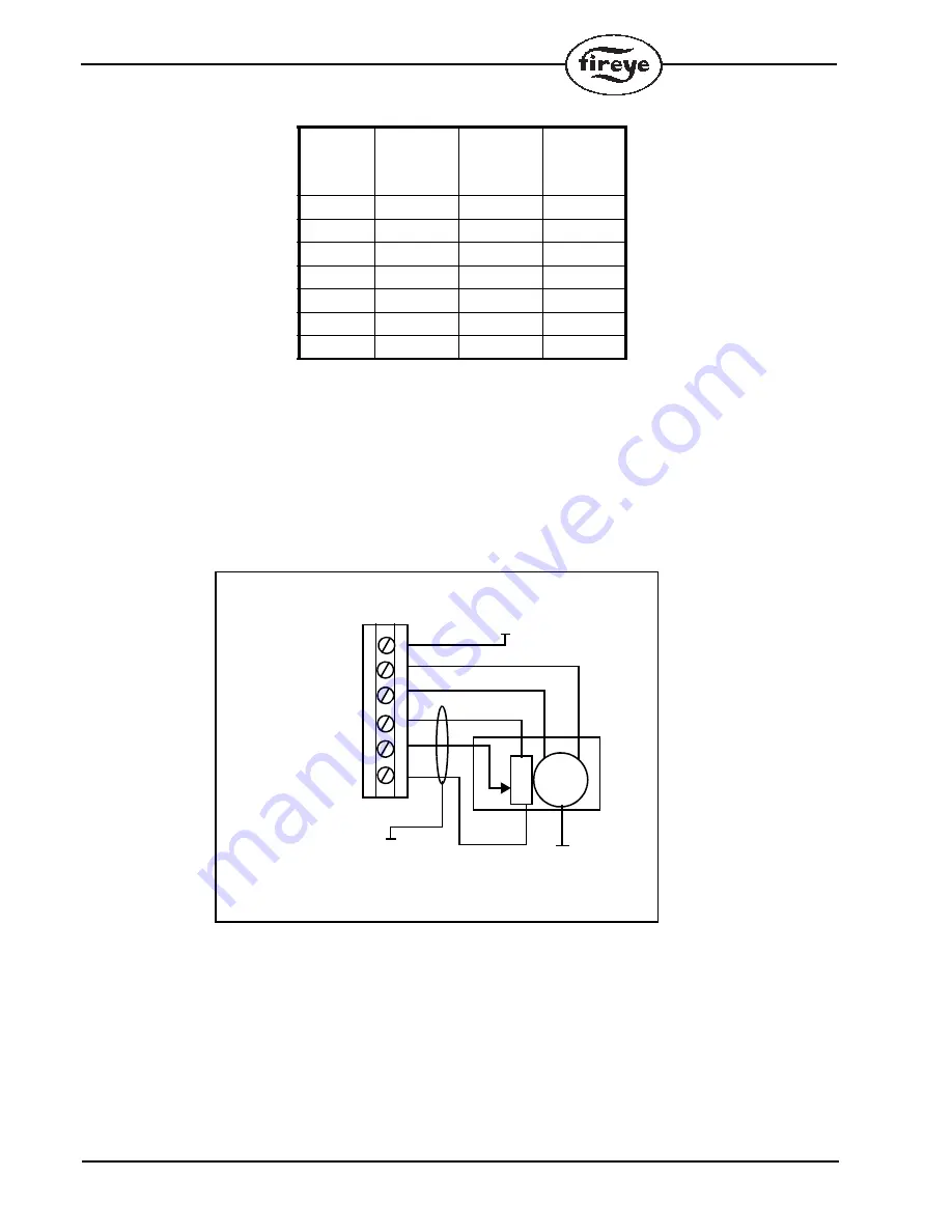
Motor Up/Down Outputs and Feedback Potentiometer Inputs
The motor up/down out-
puts should be connected
using single conductor
TEW, AWM or MTW
within the cabinet. Conduc-
tors to be pulled through
conduit should be THHN
or TFFN. Maximum wiring
size is 16 AWG. The con-
nections to the motor
should be made via its
switched inputs, so that the
internal micro switches
prevent the motor being
damaged if it is driven to
either end of its travel.
Motor feedback potentiom-
eter cabling must be overall
shielded 3-conductor PVC
insulated Belden 8735 or
similar. Since this cable may be run in conduit with the motor drive wiring, its voltage rating must
exceed the maximum voltage carried by any other cable in the same conduit.
Connect the shield with the use of the clamping bar.
Make all connections at the servo-motor first.
Incorrect connection may damage or destroy the
motor potentiometer.
PROFILE 1
INPUT
(PC13)
OFF
PROFILE 2
INPUT
(PC14)
OFF
PROFILE 4
INPUT
(PC17)
OFF
PROFILE
SELECTED
NONE
BURNER OFF
ON
OFF
OFF
1
OFF
ON
OFF
2
ON
ON
OFF
3
OFF
OFF
ON
4
ON
OFF
ON
5
OFF
ON
ON
6
ON
ON
ON
7
M
LINE/MOTOR
CABLE CLAMP
NEUTRAL/MOTOR
COMMON
SUPPLY
MOTOR COM PE 1
MOTOR UP PE 3/5/8/10
MOTOR DN PE 2/4/7/9
POT SUPPLY PD 4/10/13/18
FEEDBACK PD 3/9/12/17
POT GND PD 2/8/11/16


