background image

24

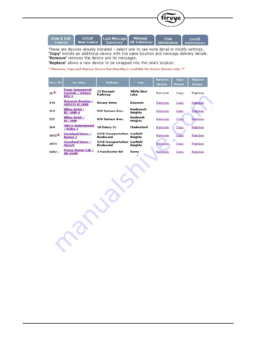
The information pertaining to that location along with the last 3 lockouts and the last heartbeat infor-
mation for the selected device will now be displayed. Remember, every inTouch device can have
multiple pieces of equipment connected and each piece of equipment must have its own Device ID.
For example, in the figure above, Dev. ID 1082 and 1083 are actually the same inTouch device at the
same physical location with two Flame-Monitors connected. Click on the location name of the
device you want to get details about.

Summary of Contents for InTouch IT1000

Page 1: ...distinct messages for each monitored point Two each of the dry contact and AC voltage inputs can be configured to alarm on contact close or open or on voltage present or absent Also every 24 hours the...

Page 2: ...outdoor mounting Dimensions 7 1 8 W x 9 5 8 H x 3 1 2 D 18 x 24 5 x 8 9cm Material UV Resistant ABS Grey Knockouts 3 bottom 3 rear 1 2 3 4 concentric Inputs RS485 Modbus RTU Protocol 4800 9600 baud se...

Page 3: ...within the range of 0 through 9 When con figuring the inTouch over the web site the device installed will be the base address of the inTouch plus the unit address of the Flame Monitor MicroM or Burne...

Page 4: ...AC power to the appropriate terminals located in the lower right corner The transmitter will begin a startup routine The startup time will vary but may last up to several minutes as the transmitter e...

Page 5: ...23 24 85 120 VAC 60 Hz 12 Use this knockout for Class I leads 13 Device wiring 22 earth ground 14 Voltage inputs 13 20 24 120 VAC or 5 48 VDC 10 11 12 19 13 14 15 16 18 17 20 23 21 24 22 15 Terminal b...

Page 6: ...ng underneath Use all three tabs to secure the unit DO NOT drill any holes into or through the enclosure Filed wiring to the inputs must be a minimum of AWG and a maximum of 12 AWG Wiring Guidelines R...

Page 7: ...ng the Device ID number Without this number the device cannot be config ured at the web site Testing To complete the test the transmitter must be configured at the Fireye web site see Configuring the...

Page 8: ...efer to Figure 6 on page 10 for an illustration overview Plug the ED512 cable into either of the telephone style jacks located in the upper left corner of the EP or EPD programmer module Refer to Figu...

Page 9: ...page 10 for an illustration overview Plug the ED512 cable into either of the telephone style jacks located in the underside of the YB110 or ZB110 module Refer to Figure 5 on page 10 Connect the other...

Page 10: ...the OPTION button 3 times The 7 seg ment LED display will switch to a dash symbol followed by the addresses of the devices it is successfully communicating The display will then show the dash symbol f...

Page 11: ...ystem provides for the connection of 4 dry contact and 4 AC inputs see Fig 1 These can be used to transmit messages when a contact is detected as closed open or power is applied not applied to the AC...

Page 12: ...will automatically see the Edit User Info screen shown in Fig 7 Otherwise you can access this screen by clicking on the menu item Edit user Info or if you know the User Info is correct move on to the...

Page 13: ...ee Fig 11 If you have any existing transmitters they will appear in a list To add your new device click on the menu item Install New Device see Fig 8 THESE ARE THE DEFAULT LOCATIONS FOR MESSAGE DELIVE...

Page 14: ...St for Street or Rd for Road if you plan to use the voice mes sage delivery Do not use uppercase letters for words if you plan to use for voice message delivery example use flow not FLOW as the synth...

Page 15: ...THE ADDRESS OF THE EQUIPMENT THE TRANSMITTER IS MONITORING THIS INFORMATION SHOULD BE COMPLETE ENOUGH TO ALLOW A SERVICE PERSON TO GET THE APPROPRIATE PARTS BEFORE COMING TO THE EQUIPMENT SITE CLICK...

Page 16: ...ow many times Fireye will attempt to deliver a message if the message is not successfully received When the message is delivered successfully no more attempts will be made If the message is not succes...

Page 17: ...bring up the Device Information screen Fig 12 A summary of the information which was entered in Fig 8 New Equipment Information appears If any of the information is not correct click on the button Ed...

Page 18: ...gured to be sent to various addresses using different delivery methods To change an existing delivery address click on any field in the Delivery Address column to change it Note the only acceptable ch...

Page 19: ...19 FIGURE 15 TO MAKE ANY CHANGES CLICK ON EDIT DELETE OR ADD...

Page 20: ...e e mail message appears below Make sure the appropriate individuals were paged that the appropriate faxes were sent and the appropriate phone calls were made Check the messages Confirm the equipment...

Page 21: ...o input the information on where the User or where the transmitter will be located Once you have filled in all the required fields click on the Submit button Credit Application The inTouch service may...

Page 22: ...HEN YOU HAVE COMPLETED THE FORM AND ARE READY TO BECOME A MEMBER THIS ADDRESS IS THE BILLING ACCOUNT ADDRESS OF THE ACCOUNT HOLDER THIS INFORMATION IS USED TO CONTACT THE ACCOUNT HOLDER THIS IS NOT WH...

Page 23: ...e passwords to them ACCESSING YOUR inTouch ACCOUNT After your inTouch device is installed and Flame Monitor or MicroM controls are properly con nected and verified you can check the historical status...

Page 24: ...Remember every inTouch device can have multiple pieces of equipment connected and each piece of equipment must have its own Device ID For example in the figure above Dev ID 1082 and 1083 are actually...

Page 25: ...h Also from this page you are allowed to edit the device infor mation such as the contact person and phone number or description of equipment For instance when you click on the one of the last 3 locko...

Page 26: ...stablished to transmit to the message server after 1 00 AM However due to signal levels below the minimum required the inTouch system was not able to consistently report in at its regular time When st...

Page 27: ...27 You can also click on any of the stored lockouts to get a view of the message delivery of that particu lar lockout...

Page 28: ...s found defective in material or workmanship or which otherwise fails to conform to the description of the product on the face of its sales order THE FOREGOING IS IN LIEU OF ALL OTHER WARRANTIES AND F...

Reviews: