


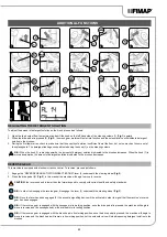


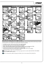


EXTRA BRUSH HEAD PRESSURE
This machine is capable of increasing the pressure exerted upon the brushes during the work cycle. This can be done in the following manner:
1.
Check to make sure that the brush head body is in contact with the floor. If this is not the case, adjust the brush head control lever (4) on the
steering column (
Fig.4
).
2. Engage the “EXTRA-PRESSURE ACTIVATION/DEACTIVATION” lever (5) underneath the steering wheel (
Fig.5
).
3. Press the drive pedal (2) (
Fig.2
), and the machine will begin to work.
N.B.:
Once the lever (5) has been engaged, the red indicator light (6) on the steering column will turn on to indicate that the extra-
pressure function has been enabled (
Fig. 6
).
BUZZER
The machine is equipped with an acoustic signalling device. If an acoustic signal needs to be emitted, simply press the button (7) on the control
panel (
Fig.7
).
WORKING HEADLIGHTS (OPTIONAL)
Upon request, the machine can be equipped with front and rear working lights. These lights can be turned on by setting the main switch to “I”, by
turning the key (8) a quarter turn to the right (
Fig.8
).
EMERGENCY BUTTON
If any problems are encountered during work operations, press the emergency button (9) on the carter that covers the electrical system (
Fig.9
).
CAUTION:
This command interrupts the electrical circuit between the batteries and the machine system.
N.B.:
After having stopped and resolved the problem, the work operations can be resumed by doing the following:
1. Bring the main switch to the "0" position by turning the key (8) a quarter turn anti-clockwise (
Fig.10
).
2. Move the mushroom-head emergency button (9) forwards (
Fig.11
).
3. Bring the main switch to the "I" position, turning the key (8) a quarter turn clockwise (
Fig.8
).
BRAKING CONTROL
The machine has an encoder to help braking and also a mechanical brake. If the machine is moving and the accelerator pedal (2) is released,
the machine brakes, decelerating gently, until it stops the encoder. Only when the encoder has stopped is the electric brake engaged. If the
machine is moving and the brake pedal (10) (
Fig.12
) is pressed, the machine brakes according to the braking force of the mechanical system.
Only when the encoder has stopped is the electric brake engaged.
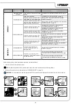
ALARM SCREEN
If there is an error, the writing AL is shown on the control display followed by a number (
Fig.13
), this stays visible until the error is resolved.
When an error occurs, do as follows:
1. Stop the machine immediately.
2.
If the error persists, switch off the machine, wait for at least ten seconds and switch on the machine.
3. If the error persists contact the nearest service centre.
List of alarms:
NUMBER
TYPE
DESCRIPTION
AL_1
General
Memory error
AL_2
General
Key fault
AL_3
General
Undervoltage
AL_4
General
Overvoltage
AL_5
General
Batt. connection
AL_6
General
Dashboard communication
AL_7
General
FFM communication
AL_8
General
Internal communication 1
AL_9
General
Internal communication 2
AL_10
General
Enter tag
AL_11
General
Invalid tag
AL_12
General
Update in progress…
AL_13
General
Switch-off
AL_14
General
Recovery tank full
NUMBER
TYPE
DESCRIPTION
AL_15
General
Brake fluid Reserve
AL_41
Function
Overtemperature
AL_42
Function
Power board damaged
AL_43
Function
Main fuse faulty
AL_44
Function
Main contactor faulty
AL_45
Function
Main contactor faulty - CC
AL_46
Function
Overcurrent - brush outputs 1-2-3
AL_47
Function
Overcurrent - vacuum cleaner outputs 1-2
AL_48
Function
Overcurrent - water pump outputs
AL_49
Function
Amperometric - brush output 1
AL_50
Function
Amperometric - brush output 2
AL_51
Function
Amperometric - brush output 3
AL_52
Function
Amperometric - vacuum cleaner output 1
AL_53
Function
Amperometric - vacuum cleaner output 2
24