


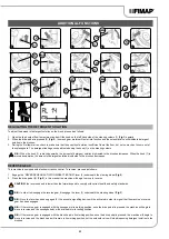


3. Turn the brush head control lever (6) anti-clockwise (
Fig.8
); in this manner the brush head body will be raised off the floor.
4. Once the brush head body has arrived in its resting position, perform the procedure for securing the machine (see the section entitled
WARNING:
It is recommended to wear the appropriate PPE (Personal Protective Equipment), suitable for the work to be carried out.
5. Move to the left hand side of the machine and open the left lateral carter (3) (
Fig.3
).
6. With the brush head UP, insert the brush in the plate housing underneath the brush head, turning it until the three buttons engage with the
niches on the plate itself.
7. Turn in increments until the button is pushed towards the coupling spring and is locked in place (
Fig.24
).
N.B.:
Image 24 indicates the direction of rotation for coupling the left brush; the right brush must be turned in the opposite direction.
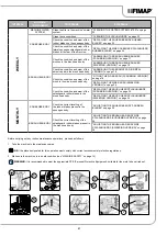
FITTING THE SIDE BRUSH (SCRUBBING VERSION)
For packaging reasons, the side brush comes disassembled from the machine, and must be assembled on the brush head body by doing the
following:
1. Sit on the driver’s seat.
2. Insert the key (2) into the main switch on the control panel and move the main switch to position "I" by turning the key a quarter turn
clockwise (2) (
Fig.7
).
3. Check to make sure that the side brush head body is in its resting position, otherwise press the side brush control button (28) on the left-
hand side of the steering column (
Fig.25
).
4. Once the brush head body has arrived in its resting position, perform the procedure for securing the machine (see the section entitled
WARNING:
It is recommended to wear the appropriate PPE (Personal Protective Equipment), suitable for the work to be carried out.
5. With the brush head in the rest position, insert the brush into the plate housing underneath the brush head, and turn it until the two buttons
(29) engage with the recesses on the plate itself (
Fig. 26
).
6. Push the brush until the stopper spring on the brush itself has engaged with the niche present on the gearmotor pin.
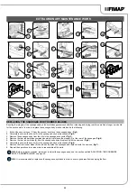
ASSEMBLING THE BRUSH HEAD BRUSHES (SWEEPING VERSION)
To assemble the brushes to bush head body, which for reasons of packaging are supplied dismantled from the machine, proceed as follows:
1. Sit on the driver’s seat.
2. Insert the key (2) into the main switch on the control panel and move the main switch to position "I" by turning the key (2) a quarter turn to
the right (
Fig.7
).
3. Turn the brush head control lever (6) anti-clockwise (
Fig.8
); in this manner the brush head body will be raised off the floor.
4. Once the brush head body has arrived in its resting position, perform the procedure for securing the machine (see the section entitled
WARNING:
It is recommended to wear the appropriate PPE (Personal Protective Equipment), suitable for the work to be carried out.
5. Open the machine's left lateral carter (3) (
Fig.3
).
6. With the brush head in its resting position, turn the knobs (30) that hold the left lateral carter (31) in place anti-clockwise (
Fig.27
).
7. Remove the left lateral carter (
Fig.28
).
8. Insert the brush into the tunnel (
Fig.29
), taking care to make sure that the gearmotor's drive shaft enters the slit in the brush itself.
9. Repeat the previously described operations for the right-hand side as well.
N.B.:
In order to be installed correctly, the brushes must form an X when viewed from above in the forward direction of movement
(
Fig.30
).
ASSEMBLING THE ABRASIVE PAD (ORBITAL VERSION)
For packaging reasons, the abrasive pad comes disassembled from the machine (if requested on the purchase order), and must be assembled
on the brush head body by doing the following:
1. Sit on the driver’s seat.
2. Insert the key (2) into the main switch on the control panel and move the main switch to position "I" by turning the key (2) a quarter turn to
the right (
Fig.7
).
3. Turn the brush head control lever (6) anti-clockwise (
Fig.8
); in this manner the brush head body will be raised off the floor.
4. Once the brush head body has arrived in its resting position, perform the procedure for securing the machine (see the section entitled
WARNING:
It is recommended to wear the appropriate PPE (Personal Protective Equipment), suitable for the work to be carried out.
5. Move to the right-hand side of the machine and open the right lateral carter (32) (
Fig.31
).
18