


WARNING:
It is recommended to wear the appropriate PPE (Personal Protective Equipment), suitable for the work to be carried out.
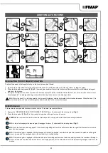
5. Unscrew the knobs (16) in the squeegee body pre-assembly (
Fig.16
).
6. First, insert the left pin (17) on the squeegee body into the left slit (18) in the squeegee support (
Fig.17
), so that the bushing adheres to the
walls of the slit in the squeegee support.
7. Repeat the same operation for the right pin.
8. Insert the vacuum hose (19) in the sleeve (20) on the squeegee body (
Fig.18
).
N.B.:
Although the squeegee comes pre-adjusted, it is nevertheless recommended to read the section entitled “ADJUSTING THE
SQUEEGEE BODY’S RUBBER BLADES” on page 35.
INSERTING WATER SYSTEM FILTER
Before using the machine for the first time the water system filter needs to be reset, for shipping reasons the filter cartridge and the cap have
been removed. To insert the filter cartridge in the water system filter body proceed as follows:
1. Take the machine to the maintenance area.
2. Carry out the steps to ensure the machine is in a safe condition (read “MACHINE SAFETY” on page 14.
CAUTION:
It is recommended to wear the appropriate PPE (Personal Protective Equipment), suitable for the work to be carried out.
3.
Close the tap's output flow, and shift the knob (21) on the left hand side of the steering column (
Fig.19
) downwards.
4.
Move to the front of the machine, insert the filter cartridge (22) in the housing on the cap (23) (
Fig.20
).
N.B.:
The O-ring gasket in the filter cartridge should be inserted into its seat in the cap.
5.
Screw the cap (23) onto the body of the detergent solution filter (
Fig.21
).
FILLING THE SOLUTION TANK
Before filling the solution tank, carry out the following steps:
1.
Take the machine to the usual place for filling the solution tank.
2. Carry out the steps to ensure the machine is in a safe condition (read “MACHINE SAFETY” on page 14.
3. Check to make sure that the solution tank drainage cap (24) is closed. If this is not the case, close it (
Fig.22
).
4.
Check to make sure that the water system's filter cap (23), located on the rear left-hand side of the machine, is closed; if not, close it
(
Fig.21
).
The solution tank can be filled with water in two different ways:
•
Removing the cap/measuring device (25) and filling the solution tank by means of a rubber hose or a bucket (
Fig.23
).
•
Using the filler hose (26) (
Fig.23
), which supports the water hose on its own, be sure to remove the cap-measuring device (25) in order to
allow the air to vent properly.
5. Fill with clean water, at a temperature not higher than 50°C and not lower than 10°C. The amount inside the tank can be seen by means of
the level tube (27) on the left-hand side of the machine (
Fig.23
).
DETERGENT SOLUTION
After filling the solution tank with clean water add the liquid detergent to the tank in the concentration and manner indicated on the detergent
manufacturer's label. To prevent the formation of an excessive amount of foam that could damage the vacuum motor, use the minimum
percentage of detergent required.
WARNING:
protective gloves should always be worn before handling detergents or acidic or alkaline solutions, to avoid serious injury to
the hands.
ATTENTION:
always use detergents whose manufacturer's label indicates their suitability for scrubbing machines. Do not use acid or
alkaline products or solvents without this indication.
ATTENTION:
always use low-foam detergent. To avoid the production of foam, put a minimum quantity of antifoam liquid in the recovery
tank before starting to clean. Do not use pure acids.
ATTENTION:
The filler cap can be used as measuring device for the detergent to be added to the solution tank; the cap features moulded
notches identifying the percentage of detergent, ranging from a minimum of 0.1% to a maximum of 0.5%.
ASSEMBLING THE BRUSH HEAD BRUSHES (SCRUBBING VERSION)
To assemble the brushes to bush head body, which for reasons of packaging are supplied dismantled from the machine, proceed as follows:
1. Sit on the driver’s seat.
2. Insert the key (2) into the main switch on the control panel and move the main switch to position "I" by turning the key a quarter turn
clockwise (
Fig.7
).
17