background image

12


Removing or Installing the Right Side Sliding 

Fence (Fig. 19)


1. Unlock the fence cam-locking lever, and slide the 

sliding fence to the right.


2. Remove the hex screw (3) by a using a 3 mm hex 

key.


3. Lift up on the sliding fence to remove it from the 

saw.


4. Replace the sliding fence and thread the hex screw 

to lock the sliding fence when not making right bevel cuts.


Compound Cut (Fig. 20)


1. Extending the fence by sliding it out to the required 

location or remove the right sliding fence if necessary.


2. Set the desired bevel angle using the bevel lock 

handle (2).


3. Set the desired mitre angle and lock into position. 

See “MITRE CUT”.


Base Moulding Cut (Fig. 21)


1. Base moulding can be cut vertical against fence or 

flat on the table. Follow the table below for reference.

SETTINGS

Vertical Position 

(Back of moulding is 

against the fence)

Horizontal Position 

(Back of moulding is 

flat on the table)

Extension Fence

Close to the blade

Far from the blade

Bevel Angle

45°

Moulding Position

Left side

Right 

side

Left side

Right 

side

Inside 

Corner

Mitre 

Angle

Left at 

45°

Right at 

45°

Moulding 

position

Bottom 

against 

table

Bottom 

against 

fence

Top 

against 

fence

Bottom 

against 

fence

Finished 

side

Keep left 

side of 

cut

Keep 

right side 

of cut

Keep left 

side of 

cut

Keep left 

side of 

cut

Outside 

Corner

Mitre 

Angle

Right at 

45°

Left at 

45°

Moulding 

position

Bottom 

against 

table

Bottom 

against 

table

Bottom 

against 

table

Top 

against 

fence

Finished 

side

Keep left 

side of 

cut

Keep 

right side 

of cut

Keep 

right side 

of cut

Keep 

right side 

of cut


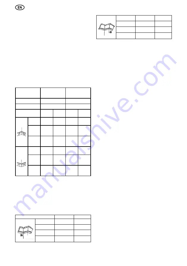
Crown Moulding Cut (Fig. 22)


1. Crown moulding can only be cut flat on the table for 

this mitre saw.


2.  This  mitre  saw  has  special  mitre  stops  of  31.6° 

left and right and a bevel stop of 33.9° for a special crown 

moulding, i.e. 52° between the back of the moulding and 

the top flat surface that fits against the ceiling; 38° between 

the back of the moulding and the bottom flat surface that 

fits  against  the  wall.  Refer  to  the  following  table  for  this 

crown moulding cut.

SETTINGS

Left Side

Right Side

Inside Corner

Mitre Angle

31.6° Right

31.6° Left

Bevel Angle

33.9°

33.9°

Moulding

Position

top against

fence

bottom against

fence

Finished Side

Keep left

side of cut

Keep left

side of cut

Outside Corner

Mitre Angle

31.6° Left

31.6° Right

Bevel Angle

33.9°

33.9°

Moulding

Position

bottom against

fence

top against

fence

Finished Side

Keep right side

of cut

Keep right side

of cut


NOTE:


1. These special stops can not be used with 45° crown 

moulding.


2. Since most rooms do not have angles of exactly 

90°,  fine  tune  is  needed  and  always  take  a  test  cut  to 

confirm the correct angles.


Pullover Cut (Fig. 23)

 WARNING!

-  Never  pull  the  cutting  head  assembly  and  spinning 

blade toward you during the cut. The blade may try to climb 

up on the top of the workpiece, causing the cutting head 

assembly and spinning blade to kick back.

-  Never lower spinning saw blade down before pulling 

the cutting head to the front of the saw.


1. Unlock the carriage lock handle (1) and allow the 

cutting head assembly to move freely.


2. Set both the desired bevel angle and/or the mitre 

angle and lock into position.


3. If bevel cutting, set both the left and right sliding 

fences (2) to their proper location.


4. Use a hold down clamp to secure the workpiece.


5. Grasp the saw handle (3) and pull the carriage (4) 

forward until the centre of the saw blade is over the front of 

the workpiece (5).


6. Pull the trigger (6) to turn the saw on.


7. When the saw reaches full speed, push the saw 

handle down, slowly, cutting through the leading edge of 

the workpiece.


8.  Slowly  move  the  saw  handle  toward  the  fence, 

completing the cut.


9.  Release  the  trigger  and  allow  the  blade  to  stop 

spinning before allowing the cutting head to raise.


Setting Cutting Depth (Fig. 24)


The depth of cut can be preset for even and repetitive 

shallow cuts.


1. Adjust the cutting head down until the teeth of the 

blade are at the desired depth of cut.


2. While holding the upper arm in position, turn the 

stop knob (1) until it touches the stop plate (2).


3.  Recheck  the  blade  depth  by  moving  the  cutting 

head front to back through the full motion of a typical cut 

along the control arm.


The Arbour Laser Guide


Your tool is equipped with our latest innovation, the 

Arbour  Laser  Guide,  a  battery  powered  device  using 

Class 1M laser beams. The laser beams will enable you 

to preview the mitre blade path on the workpiece to be cut 

before you begin your operation.

 DANGER! 

Laser is activated when blade is rotating. 

Do  not  stare  into  beam  or  view  directly  with  optical 

instruments.  Do  not  remove  the  warning  label  affixed 

to the blade guard. Avoid direct eye contact with light 

source.

 NOTE:

 The red laser line will appear as a dotted line 

when the motor is activated and the blade assembly is in 

the uppermost position. This broken line will assist you in 

aligning the mark on your workpiece with the cutting path 

of the saw blade. As you lower the blade assembly, the 

Summary of Contents for SRF305/1800

Page 1: ...SLIDE COMPOUND MITRE SAW SCIE ONGLET RADIALE KAPP UND GEHRUNGSS GE SRF305 1800 INGLETADORA TELESC PICA TRONCATRICE SRF305 1800E...

Page 2: ...2 26 Mod SRF305 1800E Fig 3 1 2 3 Fig 6 1 Fig 6...

Page 3: ...3 4...

Page 4: ...Fence Mitre at 45 bevel at 0 Mitre at 0 bevel at 45 Fig 21 3 2 1 Fig 20 OR OL IR IL Mitre saw table Fence Outside corner Inside corner Compound cut crown molding Fig 22 1 2 Fig 24 1 3 2 Fig 25 5 Fig 2...

Page 5: ...5...

Page 6: ...ties ensure these are connected and properly used Use of these devices can reduce dust related hazards 4 Power tool use and care a Do not force the power tool Use the correct power tool for your appli...

Page 7: ...njuries could occur when this tool tips over or when coming in contact with the saw blade 17 Never use the mitre saw near flammable liquids vapors or gases 18 Remove all nails that may be in the workp...

Page 8: ...ould always be carried by two persons in order to avoid back injuries Unlocking the Slide Carriage Fig 2 After removing the saw from the carton loosen the slide carriage lock knob 1 When transporting...

Page 9: ...3 Check for blade clearance by moving the slide carriage through the full motion of the blade in the table slot SETTING THE TOOL NOTE This tool is accurately adjusted before shipping from the factory...

Page 10: ...e of the ten positive stops To lock the table at all other degrees see next section Quick Cam Mitre Table Lock Operation Fig 16 If mitre angles required are NOT one of the nine positive stops noted ab...

Page 11: ...the collapsed position pushing back the lever NOTE Secure the sliding fence in position closest to the saw blade when transporting the saw Sliding Carriage System Fig 17 WARNING To reduce the risk of...

Page 12: ...Finished Side Keep right side of cut Keep right side of cut NOTE 1 These special stops can not be used with 45 crown moulding 2 Since most rooms do not have angles of exactly 90 fine tune is needed an...

Page 13: ...9 mm reducer to mount onto the saw Installing Blade Un plug the mitre saw before changing installing the blade 1 Install a 305 mm blade with a 15 9 mm arbour or a 25 4 mm arbour with a 15 9 mm reducer...

Page 14: ...en to a technical service centre if the power falls Tool inspection Using a worn tool will reduce the efficiency of the work being performed and could lead to motor damage and the tools should be chan...

Page 15: ...en el interruptor o enchufarlas con el interruptor en posici n de encendido puede provocar accidentes d Retirar toda llave de regulaci n antes de encender la herramienta el ctrica Una llave dejada en...

Page 16: ...nte deben ser almacenados y transportados en su embalaje protector y con la materia prima 12 El operador de la m quina debe estar familiarizado con sus opciones 13 Asegurar que el puesto de trabajo si...

Page 17: ...de fijaci n para cortar en inglete bajo 45 9 Inserto de la barra 10 Dispositivo de fijaci n para cortar en inglete 11 Indicador de la posici n inclinada 12 Orificios de montaje 13 Mesa giratoria 14 S...

Page 18: ...inserto 2 Para remontarlo coloque el inserto en la ranura y atornille los seis tornillos firmemente de nuevo 3 Examine la distancia desde la hoja cortante mediante la realizaci n de un movimiento com...

Page 19: ...ia el limitador 2 Comprobar si el limitador est en ngulo de 90 hacia la hoja 5 Si es necesario mueva hacia adelante o hacia atr s el limitador hasta que est perpendicular a la hoja Apriete los cuatro...

Page 20: ...l uso accidental y a continuaci n elimine los desechos peque os del corte Encendido fig 1 Para poner en marcha apretar el interruptor de conexi n desconexi n 5 y mantenerlo apretado Al soltar el inter...

Page 21: ...ngulo a 33 9 para molduras decorativas especiales lo que significa que entre la parte trasera de la moldura y el techo en el que descansa la superficie lisa superior se forma un ngulo de 52 entre la...

Page 22: ...dimiento para recambiar la hoja incluyendo el posicionado siempre debe hacerse con cuidado y correctamente No utilice discos que no est n recomendados en este manual de instrucciones Extracci n de la...

Page 23: ...alizar una evaluaci n precisa de las cargas de vibraci n experimentadas durante un per odo de trabajo concreto tambi n deber tener en cuenta los per odos de tiempo intermedios en los que el dispositiv...

Page 24: ...eau avec l interrupteur en position On peut provoquer des accidents d Enlever toute cl de r glage avant d allumer l outil lectrique Une cl laiss e fi x e une partie pivotante de l outil lectrique peut...

Page 25: ...ussi res nuisibles la sant gants de protection lors de la manipulation des lames de scie et des mat riaux bruts coupants 12 L op rateur doit tre correctement form l usage au r glage et au fonctionneme...

Page 26: ...is la scie onglets par l interrupteur manche le bras de coupe ou de la mitre manche Utilisez TOUJOURS d sign poign e de transport 1 and 23 Fig 1 D verrouillage du chariot coulissant Fig 2 Sortez la sc...

Page 27: ...vis et resserrez les 3 Pour v rifier le libre passage de la lame d placez le chariot coulissant sur toute sa course et maintenez la lame dans la fente de la table IR GLAGE DE L OUTIL REMARQUE cet out...

Page 28: ...uis un certain temps rev rifiez la perpendicularit de la lame et r ajustez la si n cessaire R glage des but es d onglet fixes Fig 16 1 D verrouillez la table de la scie onglet en soulevant le disposit...

Page 29: ...e la pi ce et de copeaux lors d un d marrage involontaire de scie d barrassez toujours la table apr s le travail et d branchez l alimentation lectrique D coupe de baguettes Fig 17 1 Desserrez sens hor...

Page 30: ...us pour cette d coupe de corniche R GLAGES C t gauche C t droit Coin int rieur Angle d onglet 31 6 droite 31 6 gauche Angle biseaut 33 9 33 9 Position de la moulure Partie sup contre le guide Partie i...

Page 31: ...dans le pr sent manuel d instructions Retrait des lames 1 D branchez la scie 2 Placez le bloc lame en position haute 3 Relevez le prot ge lame inf rieur en plastique transparent 1 jusqu la position ma...

Page 32: ...r guli rement dans des circonstances particuli res Remarque Si vous voulez effectuer une valuation pr cise des charges de vibration exp riment es au cours d une p riode de travail concr te vous devrez...

Page 33: ...trico in situazioni impreviste f Vestirsi in modo appropriato Non indossare vestiti larghi o gioielli Tenere capelli indumenti e guanti distanti dalle parti in movimento Vestiti larghi gioielli o cape...

Page 34: ...costruttore Riparazioni sono svolte soltanto dal costruttore o autorizzate persone dallo stesso 15 Aspettate che la macchina sia interamente ferma e la testa tagliante in posizione STOP prima di rimu...

Page 35: ...fissaggio per taglio con inclinazione al 45 9 Inserto per la sbarra 10 Attrezzo di fissaggio per taglio su inclinazione 11 Indicatore per posizione inclinata 12 Fori di montaggio 13 Pianale rotante 1...

Page 36: ...ei viti 1 sull inserto e rimuoverli in conseguenza ritirare l inserto 2 Per montarlo al posto collocare l inserto nella fenditura e avvitare saldamente le sei viti 3 Controllare la distanza del disco...

Page 37: ...squadra 3 Collocare come dimostrato la parte angolare del goniometro al disco di taglio la parte lineata verso il limitatore 2 Verificare se il limitatore trovasi sotto angolo 90 in rapporto al disco...

Page 38: ...tensile in funzione Arrestare la sega aspettare fino a che il disco della sega fermo togliere la spina dalla presa di corrente Inserire la sicura sull interruttore per proteggere i bambini ATTENZIONE...

Page 39: ...gia la superficie inferiore liscia si forma angolo di 38 Al taglio di strisce decorative simili usare la tabella seguente Regolazioni Parte sinistra Parte destra Coin int rieur Smusso orizzontale 31 6...

Page 40: ...ccomandati nel presente Manuale d uso Rimozione del disco di taglio 1 Disinserire la spina dalla presa prima di scambiare il disco di taglio 2 Sollevare la macchina in posizione superiore 3 Sollevare...

Page 41: ...sidera realizzare una valutazione precisa dei carichi di vibrazione registrati durante un determinato periodo di lavoro si dovr anche tener conto dei lassi di tempo intermedi nei quali il dispositivo...

Page 42: ...lteter Stellung kann zu Unf llen f hren d Einstellschl ssel vor Einschalten des Elektrowerkzeugs entfernen Sollte ein Schl ssel an einem Drehteil des Elektrowerkzeugs verbleiben so kann dies zu Verlet...

Page 43: ...r darf kein anderer Lasertyp verwendet werden Reparaturen d rfen nur vom Laserhersteller oder von einem zugelassenen qualifizierten Vertreter vorgenommen werden Versuchen Sie w hrend dem Betrieb der M...

Page 44: ...Tragen niemals am Schaltergriff am Schneidarm oder am Kegelgriff gehalten werden Tragen Sie es IMMER nur am daf r vorgesehenen Tragegriff 1 and 23 Abb 1 Entriegeln Des Zugs gearmes Abb 2 Nachdem Sie...

Page 45: ...aubendrehers die 6 Schrauben 1 an der Einlage 2 und entnehmen dann die Schrauben und danach die Tischeinlage 2 Zum Wiedereinbau legen Sie die Tischeinlage ein und schrauben diese mit den 6 Schrauben w...

Page 46: ...bitte einen Werkzeugschl ssel zur Hand Nun l sen Sie die vier Schrauben 1 am Anschlag eine volle Umdrehung so dass der Anschlag lose ist 3 Dr cken Sie jetzt den S gearm in die untere Position und ras...

Page 47: ...cke nicht verwenden K rperhaltung und Position der H nde Abb 33 Achten Sie stets darauf mit Ihren H nden nicht in den Arbeitsbereich der S ge zu geraten Ihre H nde m ssen sich stets au erhalb des gek...

Page 48: ...Rechte Seite des Schnittes Linke Seite des Schnittes Linke Seite des Schnittes AuBen kannte Gehrung Rechts auf 45 Links auf 45 0 0 Moulding position Flach auf Sagetisch Flach auf Sagetisch Flach auf S...

Page 49: ...ten Sie die S ge wieder ein und berpr fen Sie erneut die bereinstimmung von Markierung und Laserstrahl 6 Stimmt der Laserstrahl mit der Markierung auf dem Werkst ck berein sichern Sie das Werkst ck mi...

Page 50: ...weichen Pinsel oder hnliches Werkzeug um S gemehl und Sp ne zu entfernen WECHSEL DES ZAHNRIEMENS Fig 29 30 Achtung Bevor Sie mit dem Wechsel des Zahnriemens beginnen ziehen Sie bitte den Netzstecker...

Page 51: ...ein wenden Sie sich zur Durchf hrung des Austauschs an eines der Kundendienstcenter Verwenden Sie nur Originalzubeh r und Originaler satzteile von FELISATTI Jene Teile die in der Bedie nungsanleitung...

Page 52: ...52 1 b 2 b d f 3 b d f g 4 b d...

Page 53: ...EN847 1 7 8 9 10 11 12 13 14 15 16 17 18 19 20 21 INTERSKOL Power Tools S L Crta de Sant Joan de les Abadesses s n 17500 Ripol Girona Spain TC RU C TW ME77 B 00186 08 11 2012 16 10 2017 141400 29 09...

Page 54: ...342 305 30 60T ATB 305 30 80T ATB 305 30 80T TCG 305 30 80T ATB 2 3 4500 1 ATB 5000 1 TCG 0 15 22 5 31 6 45 0 15 22 5 31 6 45 60 45 60 0 45 EPTA 01 2003 34 33 102 310 45 102 222 60 102 x158 45 L 60 31...

Page 55: ...55 1 1 3 1 2 2 3 1 1 3 1 2 3 2 3 4 1 1 2 2 3 5 1 1 2 3 2 5 3 1 2 6 1 1 2 2 6 1 SRF305 1800E 1 1 2 2 7 1 2 1 8 1 2 9 1 1 2 2 3 1 5 4 5 18 5 18 1 3 18 4 6 6 18 4 6 6 6 6 6 4 1 1...

Page 56: ...0 2 10 0 1 10 13 1 12 33 9 0 13 1 10 1 12 2 10 4 1 1 12 4 13 1 10 1 1 10 2 10 10 1 11 0 2 0 3 1 45 12 13 14 1 10 1 1 12 2 4 14 3 45 4 45 5 12 6 12 5 6 45 7 5 12 45 12 13 14 1 10 1 1 12 2 4 14 3 45 4 4...

Page 57: ...57 1 2 2 1 3 14 1 0 2 3 3 2 0 15 1 0 2 1 2 2 3 4 3 2 90 5 1 16 1 3 2 2 3 4 3 16 1 3 2 2 3 4 3 16 1 2 13 5 3 4 6 31 32 1 1 1 1 0 31 6 1 SRF305 1800E 45 6 1 1 2 3...

Page 58: ...58 Zmax 0 32 FELISATTI 1 2 10 3 1 2 33 No Hands 1 5 15 1 2 4 2 17 1 1 2 2 3 312 18 1 0 15 22 5 31 6 45 60 1 2 2 3 4 3 4 5 2 19...

Page 59: ...9 35 45 22 5 90 0 45 1 0 33 9 45 19 1 2 3 3 4 20 1 2 2 3 21 1 0 45 Gehrung 45 45 0 0 45 45 0 0 22 1 2 31 6 33 9 52 38 31 6 31 6 33 9 33 9 31 6 31 6 33 9 33 9 1 45 2 90 23 1 2 1 1 2 3 2 4 5 3 4 5 6 6 7...

Page 60: ...60 8 9 24 1 2 1 2 3 1M 0 39 400 700 60825 1 2007 1 2 3 4 5 6 1 SRF305 1800E 26 25 26 27 1 2 3 1 25 4 2 5 3 4 27 6 7 5 26 8 9 5 8 6 7 27 10 1 25 305 15 9 1 305 15 9 25 4 15 9 2 8 4 8 4 27 3 4 5...

Page 61: ...61 4 26 5 3 2 26 6 1 25 7 28 1 2 3 28 4 1 5 LR44 29 30 1 1 2 2 3 4 2 5 80 dB A SRF305 1800 SRF305 1800E 100 3 89 4 111 03 102 4 2 1 235 1 5 Y...

Page 62: ...62 40 80 FELISATTI FELISATTI...

Page 63: ......

Page 64: ...Interskol Power Tools S L Carretera de Sant Joan de les Abadesses s n17500 RIPOLL Girona SPAIN Tel 34972700200 Fax 34972700554 e mail felisatti interskol es...

Reviews: