


1 -2
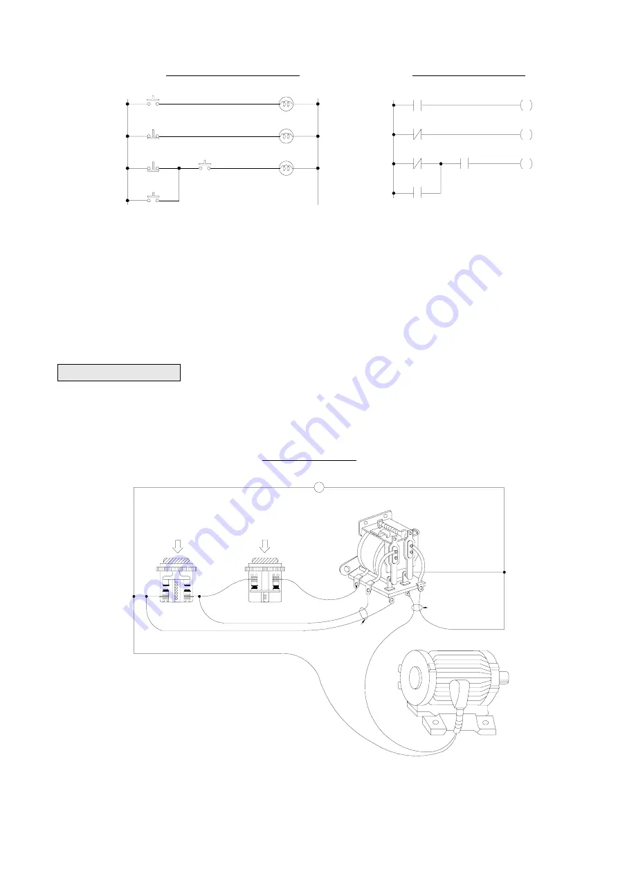
Conventional Ladder Diagram
PLC Ladder Diagram
circuit 1
circuit 2
circuit 3
X0
X1
X2
X3
X4
Y0
Y1
Y2
circuit 1
circuit 2
circuit 3
X0
X1
X2
X3
X4
Y0
Y1
Y2
The above example illustrated the combination logic using the actual wiring diagram, conventional Ladder Diagram, and
PLC Ladder Diagram. Circuit 1 uses a NO (Normally Open) switch that is also called "A" switch or contact. Under normal
condition (switch is not pressed), the switch contact is at OFF state and the light is off. If the switch is pressed, the contact
status turns ON and the light is on. In contrast, circuit 2 uses a NC (Normally Close) switch that is also called "B" switch or
contact. Under normal condition, the switch contact is at ON state and the light is on. If the switch is pressed, the contact
status turns OFF and the light also turns off.
Circuit 3 contains more than one input element. Output Y2 light will turn on under the condition when X2 is closed or X3
switches to ON, and X4 must switch ON too.
1.1.2
Sequential Logic
The sequential logic is a circuit with feedback control; that is, the output of the circuit will be feedback as an input to the
same circuit. The output result remains in the same state even if the input condition changes to the original position. This
process can be best explained by the ON/OFF circuit of a latched motor driver as shown in below.
Actual wiring diagram
NO
NC
X5
AC110V
X6
~
Y3
START switch
STOP switch
Relay
Contact 2
Contact 1
Motor
AC110V
X6
Contact 1
X5
Y3
Contact 2
Motor
Relay
STOP switch
START switch
NO
NC


