background image


FILLING THE TANKS


FILLING THE TANKS  


Utility Sprayer 25' / 30' / 40' / 45'


Page 65


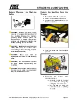
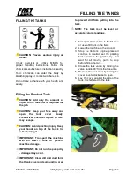
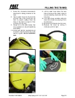
7.


Follow  the  chemical  manufacturer’s 

directions for adding chemical to the 

tank.


8.


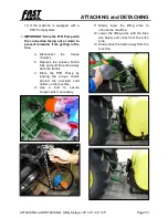
Insert a water hose into the tank. Be 

sure the hose is far enough into the 

tank  to  prevent  spilling.  Hold  the 

those  in  the  tank  to  prevent  it  from 

coming out of the tank.


9.


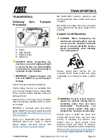
Slowly turn on the water supply. Use 

a low pressure to prevent splashing 

and spilling.


10.


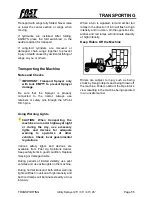
Fill the tank with the required amount 

of solution. Use the tank scale on the 

side as a guide. 

Do not overfill the 

tank.


11.


Lift  the  water  hose  above  the  tank 

before turning off the water supply to 

prevent  drawing  chemicals  into  the 

hose line. 


12.


Turn off the hose and allow all fluid to 

drain from it before removing it from 

the tank area.


13.


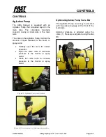
Remove and properly stow the hose.


14.


Replace  the  cover  by  turning  it 

clockwise until it is tight.


Summary of Contents for UT3P25

Page 1: ...UT3P25 30 30BL 40 45 H40 H45 UTILITY SPRAYER OWNER S MANUAL...

Page 2: ...820037 25 30 40 45 Utility Sprayer 2023 11 15...

Page 3: ...3 Wear Protec ve Clothing 23 Protect Against Noise 23 Prac ce Safe Maintenance 23 Support Raised Equipment 24 Avoid Hea ng Near Pressurized Fluid Lines 24 Avoid High Pressure Fluids 24 Inspect Li Circ...

Page 4: ...em Op ons 37 HYDRAULIC FLOW 38 Regula ng Hydraulic Flow to the Pump 38 Load Sensing Closed Center System LS Closed 38 Pressure Compensa ng Closed Center System PC Closed 38 Open Center System Open 39...

Page 5: ...g the Machine Hydraulic 60 Unfold the Boom Hydraulic 60 Fold the Boom Hydraulic 61 FIELD OPERATION 62 Adjust Ground Speed 63 Broadcast Spraying 63 FILLING THE TANKS 64 Filling the Product Tank 64 Fill...

Page 6: ...Safely 81 Lubricant Storage 81 Grease 82 Greases for Air Temperature Ranges 82 Alterna ve and Synthe c Lubricants 82 Frame Lubrica on 82 Pump Maintenance and Service 83 Filter 83 Boom Maintenance and...

Page 7: ...nk Connec on Replacement 95 PREPARING FOR STORAGE 96 Winteriza on 96 For the Foam Row Marker 96 Removing from Storage 97 TROUBLESHOOTING 98 General 98 Controller 98 Foam Maker 99 TIGHTENING HARDWARE 1...

Page 8: ...Table of Contents Utility Sprayer 25 30 40 45 Page 8...

Page 9: ...ary addressed as follows Fast Ag Solutions 4130 Commerce Boulevard Windom MN 56101 This warranty shall expire one 1 year after the date of delivery of the new machinery If these conditions are fulfill...

Page 10: ...and Lights Clean ____Wheel Drive Turns Freely ____ Review Operating and ____Lubricate Machine ____ Safety Instructions ____Check Tire Pressure ____Frame and Wings Level ____Monitors and Controllers Fu...

Page 11: ...SERIAL NUMBER _______________________________ DATE PURCHASED ______________ _____ __________ TANK SIZE CIRCLE ONE 250 Gal 300 Gal BOOM WIDTH CIRCLE ONE 25 30 40 45 BOOM FOLDING CIRCLE ONE MANUAL HYDRA...

Page 12: ...ase fittings are lubricated see LUBRICATION and MAINTENANCE section in this Manual o Inspect to be sure all nuts are tightened to proper torque and all cotter pins are spread o The tires are properly...

Page 13: ...the customer aware of all safety precautions that must be followed while using this machine o When the machine is transported on a road or highway at night or during the day accessory lights and devic...

Page 14: ...If possible operate the machine to see that it is functioning properly o Acquaint the customer with any special attachment which will help do a better job o Go over the entire machine for loose or mi...

Page 15: ...er 25 30 40 45 Page 15 Owner Register Model Number P I N Number Name Address County State Date Purchased Name Address County State Date Purchased Name Address County State Date Purchased Name Address...

Page 16: ...ay require a specific metric or inch wrench RIGHT HAND AND LEFT HAND sides are determined by facing in direction that the implement will travel when going forward WRITE PRODUCT IDENTIFICATION NUMBERS...

Page 17: ...ord must in this document indicates a mandatory requirement The use of should indicates a recommendation of that which is advised but not required WARRANTY is provided as part of Fast Ag Solutions sup...

Page 18: ...for service or repairs Substitute parts will void the warranty and may not meet standards for safe and satisfactory operation Warranty is provided as part of Fast Ag Solutions support program for cus...

Page 19: ...MAJOR COMPONENTS 1 3 Point Hitch 2 Tank 3 Tank Agitation Valve 4 Hose Reel 5 Spray Wand 6 Manual Holder 7 Breakaway Wing Clutch 8 Taillights 9 Nozzle 10 Flip Wing Section 11 Main Wing Section 12 Stain...

Page 20: ...15 Nozzle 16 Solution Lines 17 Taillights 18 Stand Forklift Tine ways 19 Section Control Valves 20 Motorized Control Valve 21 Relief Valve PTO Pump models only 22 PTO Pump PTO Pump models only 23 Hyd...

Page 21: ...MAJOR COMPONENTS MAJOR COMPONENTS Utility Sprayer 25 30 40 45 Page 21 25 Pressure Gauge 26 Cord PTO Storage 27 Valve Control Box installed in tractor cab...

Page 22: ...Manual the terms CAUTION WARNING and DANGER are used along with the Safety Alert Symbol to indicate the degree of personal safety hazard The term IMPORTANT is used to indicate that failure to observe...

Page 23: ...r radio or music headphones while operating the machine Protect Against Noise Prolonged exposure to loud noise can cause impairment or loss of hearing Wear a suitable hearing protective device such as...

Page 24: ...ystem unsupported or raised equipment could suddenly lower causing serious personal injury or death If support is not available completely lower wings and frame relieve hydraulic pressure and disconne...

Page 25: ...ent hoses Store Attachments Safely Stored attachments such as dual wheels can fall and cause serious injury or death Securely store attachments and implements to prevent falling Keep playing children...

Page 26: ...le used air conditioning refrigerants Handle Agricultural Chemicals Safely Chemicals used in agricultural applications such as fungicides herbicides insecticides pesticides rodenticides and fertilizer...

Page 27: ...provides specific details on chemical products physical and health hazards safety procedures and emergency response techniques Check the M SDS before you start any job using a hazardous chemical That...

Page 28: ...he Operator s view resulting in the machine being operated in an unsafe manner Observe Maximum Transport Speed CAUTION Be sure all bystanders are clear of Sprayer IMPORTANT Transport Sprayer only with...

Page 29: ...a safe distance away from the machine when it is moving Prior to starting the tractor discuss hand signals and what each signal means to avoid misunderstandings and confusion which could result in a s...

Page 30: ...o maintain control Properly ballast tractor for towing your machine Refer to tractor Operator s Manual and this Manual to ensure that machine can be safely transported with your tractor Be aware of he...

Page 31: ...ne in tow Use caution in traffic and in congested areas To improve stability when traveling through the field wings should be unfolded from transport position as soon as possible after leaving the roa...

Page 32: ...SAFETY SAFETY Utility Sprayer 25 30 40 45 Page 32 General...

Page 33: ...ombined with the care and concern of a capable Operator The construction of this implement may not meet all local or national requirements for transport on a public roadway In regions or countries tha...

Page 34: ...afety Operating and Maintenance information presented in this Manual Do not operate or allow anyone else to operate this equipment until such information has been reviewed Annually review this informa...

Page 35: ...ilizer Pump Drive Motor Hydraulicly driven 106 LPM 27 GPM 20 7 MPa 3000 PSI 2 Wing Folding Main 15 LPM 4 GPM 20 7 MPa 3000 PSI 3 Wing Folding Swing 15 LPM 4 GPM 20 7 MPa 3000 PSI Sprayer Weights IMPOR...

Page 36: ...1 60 m 5 3 ft 2 29 m 7 5 ft 2 29 m 7 5 ft Working Width 7 62 m 25 0 ft 9 14 m 30 0 ft 9 14 m 30 0 ft 12 19 m 40 0 ft 12 19 m 40 0 ft 13 72 m 45 0 ft Sprayer Standard Features Feature UT3P25 UT3P30 UT...

Page 37: ...04 ACE 150 HYD 2062 Max Flow 79 LPM 21 GPM 102 LPM 27 GPM 507 LPM 134 GPM Controller N A TIR RC 2 Raven SCS 450 Micro Trak SprayMate II 37 Pin harness customer supplied Greenstar Flow Control Manual R...

Page 38: ...ove hydraulic lever to Lower Retract position to start pump 6 Adjust tractor flow control until the toolbar shut off deadhead pressure is within the pump s operating parameters Note If the flow limite...

Page 39: ...e Needle Valve Setup Instructions 1 Shut off sprayer boom and agitation valves 2 Loosen jam nut on motor and back out needle valve 3 or 4 turns counterclockwise 3 Set tractor throttle to sprayer opera...

Page 40: ...CV II Pushed Forward When the tractor s SCV II is pushed forward the following functions are enabled 1 Supplies hydraulic oil flow to operate implement folding functions Figure 9 SCV II Pulled Backwar...

Page 41: ...HYDRAULIC FLOW HYDRAULIC FLOW Utility Sprayer 25 30 40 45 Page 41...

Page 42: ...unt of RV antifreeze in the tank The tank must be drained and rinsed before use Drain Filters 1 Place a pail under the filter 2 Remove the drain plug from the filter 3 Allow it to drain 4 Replace the...

Page 43: ...ch the 1 1 4 yellow hose to the inlet side of the PTO Pump a Loosen the clamp and slide the hose onto the left PTO fitting b Tighten the clamp 3 Attach the hose to the Utility Sprayer a Loosen the cla...

Page 44: ...tractor 2 Disconnect the hoses from the PTO Pump 3 Cut hoses to the length needed to fit the tractor 4 Reconnect the hoses to the PTO Pump Set the Optional Hydraulic Motor Driven Chemical Pump 1 Inst...

Page 45: ...PREPARING THE MACHINE PREPARING THE MACHINE Utility Sprayer 25 30 40 45 Page 45 Install 3 Point Hitch Bushings and Spacers Follow the diagram below for installing bushings or spacers as needed...

Page 46: ...d Use be sure that the tractor s operator station is enclosed and pressurized 5 Read and understand the Operator s Manual and all safety signs on the equipment 6 Read and understand the chemical manuf...

Page 47: ...than the 3 Point Hitch shown Consult the Owner s Manual for the 3 Point Hitch equipped on your tractor Attach the Machine to the Tractor 1 Make sure there is enough room and clearance to safely back...

Page 48: ...on the 3 Point Hitch 7 Connect the section valve controller harness a Align the plug ends b Push the plug together until it is tight 8 Connect the light harness a Open the light harness port on the tr...

Page 49: ...ers are securely seated See SCV Identification Chart for hose connections Make Proper Hose Connections WARNING Escaping fluid under pressure can penetrate the skin and cause serious injury Avoid the h...

Page 50: ...ystem a Align the PTO Pump with the PTO shaft on the tractor b Push the connector onto the shaft until it locks c Brace the torque arm against a solid member NOT a moving part of the tractor s frame i...

Page 51: ...points CAUTION Make sure that all bystanders are clear of the working area CAUTION Wait for chemical ejection to stop before approaching the machine CAUTION Use caution when lowering the machine to av...

Page 52: ...he machine 8 Disconnect the taillight wiring harness a Depress the clips on the coupling b Pull the harness connection away from its port 9 If the machine is equipped with hydraulic controls WARNING P...

Page 53: ...e line a Disconnect the torque chain s b Depress the release button fully and pull the pump away from the tractor c Store the PTO Pump by looping the torque chains around the provided cord holder on t...

Page 54: ...slopes and when turning See Observe Maximum Transport Speed BE SURE SMV emblem reflectors and warning lights are clean visible and in good condition BE SURE your safety chain has a strength rating gr...

Page 55: ...during the day use accessory lights and devices for adequate warning to operators of other vehicles Check local governmental regulations Various safety lights and devices are available from Fast Ag So...

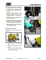
Page 56: ...all bystanders are clear of the Sprayer CAUTION Engage the parking brake with all controls in neutral and wait for all parts to stop before proceeding NOTE Wings must be unlocked at the pivot before...

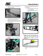
Page 57: ...in the hole on the tank s side of the boom to secure the wing in position 7 Insert the hair pin on the bottom to secure it 8 Hold the flip wing with both hands and rotate it 180 a The gas shock will p...

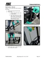
Page 58: ...ld the flip wing with both hands 2 Fold it 180 a Hold the with both hands until it is fully folded b The flip wing sits over the main wing The gas shock pulls the flip wing toward the main wing after...

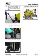
Page 59: ...th both hands and walk the main wing all the way to the Sprayer s frame 6 Insert the lock pin in the wing pivot through the top and bottom holes Put the pin in the center hole when the main wing is fo...

Page 60: ...ft and right sides of the machine unfold at the same time CAUTION Remain alert to hazards people and objects in the surrounding area and above the machine as its wings are unfolding NOTE The switch co...

Page 61: ...surrounding area and above the machine as its wings are folding NOTE The switch controlling the wings depends on the arrangement of hydraulic hoses Normally the pump is on SCV I the main wings on SCV...

Page 62: ...e if the wing section s encounters an obstacle b Confirm that the clutch is aligned correctly and lubricated Figure 13 Breakaway clutch Before use 1 Read and understand the Operator s Manual and all s...

Page 63: ...tractor Adjust Ground Speed It will be necessary to establish a travel speed and then set the flow to give the desired application rate Always run at the established travel speed Travel speed recommen...

Page 64: ...ands on top of the tank s lid when turning it IMPORTANT Transport the machine with an EMPTY tank to prevent machine damage IMPORTANT Do not run the pump dry damage may occur IMPORTANT Clean dirt and d...

Page 65: ...Slowly turn on the water supply Use a low pressure to prevent splashing and spilling 10 Fill the tank with the required amount of solution Use the tank scale on the side as a guide Do not overfill the...

Page 66: ...ot drink the water from the rinse tank The rinse tank water may become contaminated with sprayer chemicals or other contaminates Operators must always thoroughly wash according to the chemical manufac...

Page 67: ...to the boom or spray wand Partially open the valve for normal operation Open the valve more to decrease pressure to the booms or spray wand Close the valve more to increase pressure to the booms or s...

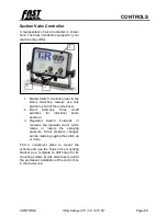
Page 68: ...olts along the track to the desired angle 3 Tighten the nuts Section Valves The section valves operate the solution flow to the boom sections Switches on the valve control box turn the boom sections o...

Page 69: ...ire boom 2 Boom Switches Three on off switches for individual boom sections 3 Regulator Switch Forwards or reverses the regulator motor which raises or lowers the spraying pressure Small pressure chan...

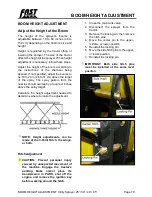
Page 70: ...m the nozzles should overlap by a couple of inches above the spray target Calculate the height adjustment needed to determine where to make the adjustment NOTE Height adjustments can be made at the 3...

Page 71: ...th the holes in the frame 9 Reinstall and tighten all bolts to secure the boom See Install 3 Point Hitch Bushings and Spacers Leveling the Booms For most accurate flow rates and performance the booms...

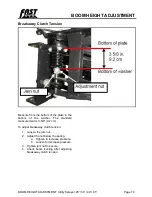
Page 72: ...tom of the plate to the bottom of the washer The standard measurement is 3 5 8 9 2 cm To adjust breakaway clutch tension 1 Loosen the jam nut 2 Adjust the nut below the spring a Tighten to increase pr...

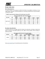
Page 73: ...ensure that there will be sufficient oil flow through the hydraulic system and sufficient power to maintain the ground speed Select the desired engine RPM and always perform the calibration and run i...

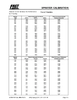
Page 74: ...SPRAYER CALIBRATION SPRAYER CALIBRATION Utility Sprayer 25 30 40 45 Page 74 However do not decrease the throttle below its 2 3 setting Travel Timetable...

Page 75: ...9 7 1 5 9 4 5 3 6 20 0 14 10 4 8 3 6 9 5 2 4 2 30 0 17 12 6 10 1 8 4 6 3 5 0 40 0 20 14 9 11 9 9 9 7 4 5 9 50 0 22 16 3 13 1 10 9 8 2 6 5 60 0 24 17 8 14 3 11 9 8 9 7 1 Boomless Spray Nozzles The spr...

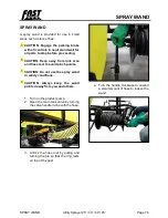
Page 76: ...Keep away from lock area and hose reel to avoid pinch points CAUTION Do not use the spray wand in windy conditions CAUTION Always keep the wand pointed away from you and others 1 Turn on the product p...

Page 77: ...ncrease wand pressure b Open the valve more to decrease wand pressure IMPORTANT Do not fully close the agitation valve while operating the wand Excess pressure may damage the product pump and spray wa...

Page 78: ...rom its hose 12 Return the wand to its holder 13 Wind up the hose by turning the reel handle counterclockwise 14 Lock the hose reel pin by pulling the pin out slightly and turning it until the ring fa...

Page 79: ...erent water sources may require different amounts of chemical concentrate to obtain the desired foam density Water hardness pH and impurities will all affect the amount of chemical concentrate require...

Page 80: ...ed b If the foam is too stiff dry it may surge out at irregular intervals Under this condition water should be added until the foam becomes softer 3 To ensure proper mixing of foam concentrate and wat...

Page 81: ...CAUTION Disconnect wiring harness from the tractor before servicing electrical system components or welding on machine CAUTION Securely support all machine elements that must be raised for service wo...

Page 82: ...istency numbers and the expected air temperature range during the service interval IMPORTANT Some types of grease thickeners are not compatible with others Consult your grease supplier before mixing d...

Page 83: ...use a wrench as this could damage the filter body At the start of each day before the water and chemicals have been added the screens should be checked and cleaned 1 Close the tank valve and agitation...

Page 84: ...Place the screens back into their filter body or bodies 8 Install the screens and bodies to the filter heads and tighten them by hand Do not over tighten and crack the filter head 9 Reinstall the dra...

Page 85: ...ve nozzle housing and remove nozzle tip 2 Clean nozzle tip with clean water 3 Reinstall nozzle tip 4 Install nozzle housing and hand tighten Wing Bumpers 1 Inspect all wing bumpers for wear and damage...

Page 86: ...be stable in the field or transport position If not replace the gas shock When unfolding or folding the main wing section you should feel resistance and the wing should be stable in the field position...

Page 87: ...the hose to completely drain into the pail a Loosen the clamp b Carefully remove the hose from the fitting c Drain the hose into the pail 5 Slowly open the tank valve and allow the tank to completely...

Page 88: ...sassembly or attempted repairs if accomplished incorrectly can create hazards Only qualified personnel should perform repair service Foamheads and Screen Strainer The foamheads have been designed so t...

Page 89: ...n the agitation pump for 10 minutes 9 Spray solutions out of booms on the appropriate crop 10 Rinse the system thoroughly with clean water and flush out the booms 11 Drain the entire system and let it...

Page 90: ...grease oil or debris On self propelled equipment disconnect the battery ground cable before making adjustments on any electrical systems or welding on the machine On towed implements disconnect its w...

Page 91: ...ely with Fast Ag Solutions approved replacement parts Escaping fluid under pressure can penetrate the skin causing serious injury Avoid the hazard by relieving pressure before disconnecting hydraulic...

Page 92: ...hoses are to be fabricated ensure that the hoses are rated at no less than 82 737 kPa 827 bar 12 000 psi burst pressure according to SAE Standard J517 100R17 hose specification Incorrect hose length o...

Page 93: ...1 Twist socket 2 to remove light 2 Replace bulb 3 Insert socket into light assembly and twist to lock 4 Connect taillight wiring harness 1 To replace the light assembly 1 Remove broken light socket 2...

Page 94: ...reel handle b Slide the hose off its fitting c Remove the clamp d Loosen the support clamp and slide the hose through e Unwind the hose from its reel 5 Install the new hose a Start the hose from the f...

Page 95: ...the hose to the fitting b Slide the hose off the fitting c Remove the clamp from hose 3 Disconnect the hose from its valve a Loosen the clamp near the spray wand handle b Slide the hose from the fitti...

Page 96: ...NCE 5 Inspect all hydraulic hoses couplers and fittings Tighten any loose fittings Replace any hose that is damaged or is separating from the crimped end of a fitting 6 Inspect all liquid lines and co...

Page 97: ...ea 2 Attach the tractor to the Sprayer 3 Check a Attach and secure all liquid lines b Row Units and Nozzles c All hardware Tighten as required d Tire pressure e All hydraulic lines fittings and connec...

Page 98: ...ch bolts Gas shock malfunctioning Replace gas shock Main wing slams hard into folded or unfolded position Gas shock malfunctioning Replace gas shock Flip wing bounces in transport or field position Ga...

Page 99: ...ure in the tank is several days old it is possible that the solution is no longer able to foam or produces little foam Drain tank rinse and start with a fresh solution 6 Check the battery connections...

Page 100: ...885 1350 1000 1700 1250 1580 1160 2000 147 5 M30 660 490 850 625 1290 950 1630 1200 1850 1350 2300 1700 2140 1580 2700 200 0 M33 900 665 1150 850 1750 1300 2200 1625 2500 1850 3150 2325 2900 2150 3700...

Page 101: ...950 700 1700 1250 2140 1580 2700 2000 3400 2500 1 1 2 990 730 1250 930 990 730 1250 930 2250 1650 2850 2100 3600 2650 4550 3350 Torque values listed are for general use only based on the strength of t...

Page 102: ...down section of the fitting 2 Install a thimble over the fitting threads to protect the O ring from nicks 3 Slide the O ring over the thimble into the turned down section of the fitting 4 Remove thim...

Page 103: ...16 12 10 6 0 375 9 53 11 16 16 13 16 24 18 1 42 31 9 16 18 3 4 3 4 37 27 25 18 12 8 0 500 12 70 13 16 16 15 16 50 37 1 1 8 93 69 3 4 16 7 8 15 16 50 37 33 25 16 10 0 625 15 88 1 14 1 1 8 69 51 1 5 16...

Page 104: ...7 Utility Sprayer UT3P25 30 30BL 40 45 H40 H45 Page 104 Fast Ag Solutions 4130 Commerce Boulevard Windom MN 56101 1 800 772 9279 Toll Free 1 507 427 3861 Voice 1 507 427 3030 Fax https fastagsolutions...

Reviews: