


Software Description
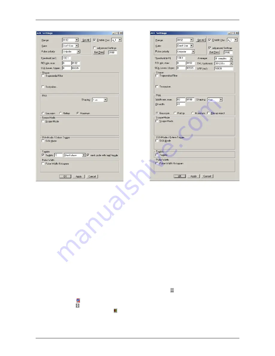
If you check advanced Settings more options will appear for the PHA parameters. VPP (mV) is the voltage
corresponding to the full range of the ADC from 0 to 65535 LSB's. You can change it if you have a calibrated
value for example by connecting a DC voltage to the ADC input that is known very well for example by using
a good digital volt meter. The THL hysteresis can be selected between “none”, “15 LSB”, “30 LSB” and “50
LSB”. The value means that the voltage level at the input must go below the threshold by the respective
value before a new pulse will be triggered. The threshold level hysteresis prevents triggering again on
spurious signals when crossing the threshold after a pulse. The recommended value depends on the noise
level, a value of 30 LSB is recommended, especially for signals that have a slow falling time and when using
the “Maximum” method.
The Fit width is the most important parameter that influences the quality of the pulse-height analysis of
Gaussian shaped pulses, see Fig. 3.9. This Fit width and the limits Width min, max for the fit range are set
when choosing a Shaping time from the list box. You may play with the Fit width parameter and see if you
can improve the resolution of your pulses by setting a value corresponding to a shaping time in between of
those in the list. If your pulses are shaped with a rather long shaping time, it could be necessary to increase
the max Width of the Fit range to get a successful PHA result.
For Flattop pulses it is necessary to specify a ROI at the top of the waveform for calculating the mean value
as PHA result, see Fig. 4.12. To get such a zoomed picture of the pulse at its top region, first switch off the
Auto scale and Minimum auto scale in the Scale options dialog of the MPANT program (Fig. 4.13). Then set
Y-Slice for the Region Shape by clicking the corresponding toolbar icon and while keeping the right mouse
button pressed, drag a zooming rectangle over the interesting region at the top of the waveform, then click
the “Zoom in” icon . To define the ROI, switch back to X-Slice for the Region Shape using the
corresponding icon . Then drag the ROI boundaries from left to right keeping the right mouse button
pressed and click the “Create ROI” icon . To take over the ROI parameters into the flattop PHA, click the
from ROI button shown in Fig. 4.14. There is a choice of anchoring the ROI either at the left edge of the
pulse, the right edge, or the left ROI boundary at a constant fraction between right and left edge, by selecting
CFT in the listbox. The edges are determined by the time when the signal crosses the threshold. It depends
F
ComTec GmbH
49
Fig. 4.11: Left: Setting Tag bits, right: advanced Settings
Summary of Contents for MCA4A
Page 2: ...2 F ComTec GmbH...
Page 8: ...8 F ComTec GmbH...
Page 71: ...Software Description F ComTec GmbH 71 Fig 4 35 Control Panel of the demo VI for LabVIEW...
Page 96: ...MPANT Software 96 F ComTec GmbH Fig 5 29 MPANT with four systems enabled...
Page 106: ...Appendix 106 F ComTec GmbH...
Page 107: ...Appendix 7 8 Personal Notes F ComTec GmbH 107...


