


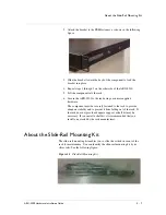


About the Slide-Rail Mounting Kit
ARX-2500 Hardware Installation Guide
2 - 9
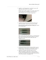
3. Install the two rail-locking brackets (found in the Accessory Kit
bubble bag) using the #6-32 screws provided.
The #6-32 screws are the 4 smaller screws. Save the 2 larger screws
to lock the chassis into the equipment rack in the final step.
The following figure shows an installed locking bracket.
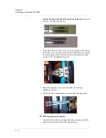
4. Assemble the front slide-rail mount brackets (the short ones) to
slide-cabinet members, using the wing (or kep) nuts provided.
Ensure the three-hole side of the bracket is facing out
(as shown
in the following figure).
Ensure the ends of the rail-mount brackets are 1 1/2 inches from the
ends of the slide-cabinet members before tightening the wing nuts.
This ensures the chassis front is flush with the front of the
equipment rack rails.
5. To determine the location of the rear-rail mount brackets, measure
the inside surface of the front rail to the inside surface of the back
rail of the equipment rack where the chassis will be installed.
6. Install the rear-rail mount brackets (the long ones) to the
slide-cabinet members, as shown below, using the wing nuts
provided. Before tightening the wing nuts, ensure the end-to-end
measurement of the slide rails of the mounting brackets matches the
rail-to-rail measurement of the equipment rack.
Summary of Contents for ARX-2500
Page 1: ...ARX 2500 Hardware Installation Guide MAN 0417 00 ...
Page 2: ......
Page 6: ...vi ...
Page 7: ...Table of Contents ...
Page 8: ......
Page 10: ...Table of Contents x ...
Page 11: ......
Page 12: ...Table of Contents xii ...
Page 14: ......
Page 22: ...Chapter 1 Introduction 1 10 ...
Page 24: ......
Page 36: ...Chapter 2 Unpacking and Installing the Switch 2 14 ...
Page 38: ......
Page 55: ...4 Maintenance POST Diagnostics ...
Page 56: ......
Page 60: ......
Page 64: ...Appendix A Replacing Optical Transceivers or Chassis A 6 ...
Page 65: ...Index ...
Page 66: ......
Page 68: ...Index Index 4 ...