Chapter 2
Unpacking and Installing the Switch
2 - 4
• ARX-2500 (1U)
• Accessory Kit (packed under the switch)
4. Verify the contents of the Accessory Kit against the following list:
• Slide-rail kit (pre-packaged, includes instructions) (1)
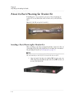
• Rack-mounting ear bracket kit (1)
• Bubble bag containing:
– Rail-locking brackets (2)
– #6-32 pan head screws (4)
– #8-32 pan head screws (2)
– RJ-45-to-DB9 adapter (1)
– Power cord retention clips (2)
– Cross-over cable (8-ft. / 2.4384-M) (1)
–
ARX-2500 Quick Installation
card
– ARX-2500 Hardware Installation Guide
If you ordered the optional optical tranceivers, they are shipped
in the Accessory Kit in their own box. The single box contains 2
optics.
In addition to the installation card and the installation guide, consult
the
ARX Hardware Reference Guide
, which includes system
specifications and requirements and details about the LEDS, cables,
external interfaces, power supplies, internal disk drives, and many
other hardware details. This guide is available in PDF form from the
ARX Manager GUI.
5. Read the instructions for determining which rail kit to use at
Determining Which Rail Kit to Use, on page 2-4
.
In particular, do not use the instructions that come with the slide-rail
mounting kit; use the instructions in this guide. These instructions
are critical to understanding how to install the rails in the rack and
set the component into the rails.
Note
Most equipment racks come with screws for mounting the chassis. You need
4 10-32 screws (5/8” to 7/8” long).
Determining Which Rail Kit to Use
The ARX-2500 platform comes with two types of rack mounting kits: a
stationary rack-mounting type and a slide-rail-mounting type. An advantage
of installing the slide-rail-mounting type is that you can then slide the
component in and out of the rack as needed.
Summary of Contents for ARX-2500
Page 1: ...ARX 2500 Hardware Installation Guide MAN 0417 00 ...
Page 2: ......
Page 6: ...vi ...
Page 7: ...Table of Contents ...
Page 8: ......
Page 10: ...Table of Contents x ...
Page 11: ......
Page 12: ...Table of Contents xii ...
Page 14: ......
Page 22: ...Chapter 1 Introduction 1 10 ...
Page 24: ......
Page 36: ...Chapter 2 Unpacking and Installing the Switch 2 14 ...
Page 38: ......
Page 55: ...4 Maintenance POST Diagnostics ...
Page 56: ......
Page 60: ......
Page 64: ...Appendix A Replacing Optical Transceivers or Chassis A 6 ...
Page 65: ...Index ...
Page 66: ......
Page 68: ...Index Index 4 ...


