


LED Indicators
ARX-2000 Hardware Installation Guide
4 - 7
Power Supply LED
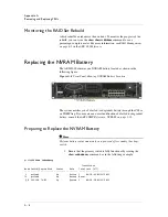
Each power supply has a single LED located to the right of the fan. The
LED locations are indicated in the following figure.
Figure 4.3
Power Supply LEDs
The following table lists and describes the power supply LED states.
Table 4.7
Power Supply LED Indicator
LED State
Power Supply Condition
Off
No AC power applied to the power supply.
Green
Power supply on and healthy.
Amber
Power supply is on but experiencing a critical event causing a
shutdown. Examples that can cause a shutdown include:
• Fan failure
• Over-voltage protection (OVP)
• Over-current protection (OCP)
In a 1+1 configuration where both power supplies are
plugged in but AC has been removed from one power supply,
the LED signal will still operate with the redundant power
supply in parallel and will, thus, be lit amber.
To bring a power supply back into full service after correcting
an error condition, remove and then re-apply AC power. This
can be as simple as unplugging the power supply and then
plugging it back in.
Blinking amber
Power supply is on and continuing to operate but
experiencing a warning condition (for example: high
temperature, high power, high current, slow fan).
The warning condition will transition to a failure and the power
supply will shut down. If you have any concerns, replace the
power supply using the instructions in the section,
Replacing
a Power Supply, on page A-11
.
Summary of Contents for ARX-2000
Page 1: ...ARX 2000 Hardware Installation Guide 810 0062 00 ...
Page 2: ......
Page 6: ...vi ...
Page 7: ...Table of Contents ...
Page 8: ......
Page 11: ......
Page 12: ...Table of Contents xii ...
Page 14: ......
Page 22: ......
Page 28: ...Chapter 2 Unpacking and Installing the Switch 2 8 ...
Page 30: ......
Page 48: ...Chapter 3 Connecting the Switch to the Network 3 20 ...
Page 49: ...4 Maintenance Powering Down the ARX 2000 LED Indicators POST Diagnostics ...
Page 50: ......
Page 60: ......
Page 72: ...Appendix A Removing and Replacing FRUs A 14 ...
Page 73: ...B Installing the Rail Kit Installing the Rail Kit ...
Page 74: ......
Page 76: ...Appendix B Installing the Rail Kit B 4 ...
Page 77: ...Index ...
Page 78: ......
Page 80: ...Index Index 4 ...


