background image

Operation, cont’d

MTPX Plus Twisted Pair Matrix Switchers • Operation

3-56


Configuration Worksheets

Rather than trying to remember the configuration for each preset, use worksheets to 

record this information.  Make copies of the blank worksheet on page 3-59 (32-input 

button and -output button switchers) and page 3-61 (16-button switchers) and 

use one for each preset configuration.  Cross out all unused or inactive inputs and 

outputs.  Use different colors for video and audio.

N

  All of the equipment in the following examples is connected through the 

appropriate MTP transmitter or receiver.

Worksheet example 1: System equipment

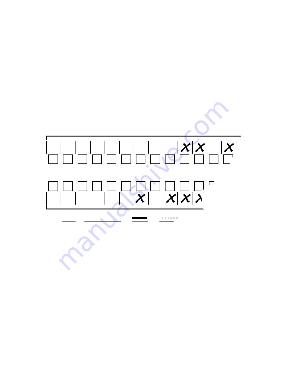
Figure 3-77 shows a portion of a worksheet for an MTPX Plus 1616 in a fictional 

organization with the system hardware annotated.  Inputs 10, 11, and 13 have no 

connection in this organization, so they are crossed out on the worksheet.  Similarly, 

outputs 7 and 9 through 16 are crossed out.

1

2

3

4

5

6

7

8

1

2

3

4

5

6

7

8

9

10

11

11

12

13

10

9

Input  sources

Output destinations 

Preset #

 Title:

 Video:

 Audio:

Fill in the preset number and use colors, dashes, etc., to make connecting lines.
Indicate if the configuration is for video, audio, or both.

Classroom

#1 VCR

USP 405

Audio

CD

PC 2 

RGB 202

PC 1 

RGB 202

Weekly status mtg 

3

Camera 

#2

Camera/ 

mic - Main

podium

Main hall

FP #1

Main hall

FP #2

Podium

monitor

Sound

system

#1

Sound

system

#2

VCR

(VSC 500)

DA 6

Classroom

#2 VCR

USP 405

Laptop

RGB 202

Rack DVD

(USP 405)

VTG 300

Figure 3-77 — Worksheet example 1: System equipment

Inputs include PCs, an audio CD player, cameras, and an Extron VTG 300.  

Output devices include monitors, projectors, a stereo, and a VCR for recording 

presentations.
The VTG 300 video test generator connected to input 12 enables a video test pattern 

to be sent to one, several, or all output devices for problem isolation or adjustment 

purposes.  An audio test tape or CD could be used in a similar manner to check out 

the audio components.

Summary of Contents for MTPX Plus Series

Page 1: ...MTPX Plus Series Mini Twisted Pair Matrix Switcher 68 1383 01 Rev B 09 08 ...

Page 2: ...enden sollten Sie alle Sicherheits und Bedienungsanleitungen genau durchlesen und verstehen Aufbewahren der Anleitungen Die Hinweise zur elektrischen Sicherheit des Produktes sollten Sie aufbewahren damit Sie im Bedarfsfall darauf zurückgreifen können Befolgen der Warnhinweise Befolgen Sie alle Warnhinweise und Anleitungen auf dem Gerät oder in der Benutzerdokumentation Keine Zusatzgeräte Verwende...

Page 3: ...ection against harmful interference when the equipment is operated in a commercial environment This equipment generates uses and can radiate radio frequency energy and if not installed and used in accordance with the instruction manual may cause harmful interference to radio communications Operation of this equipment in a residential area is likely to cause harmful interference in which case the u...

Page 4: ......

Page 5: ... 2 8 Cabling 2 9 RJ 45 connector wiring 2 9 Reset button 2 10 Power connection 2 10 Front Panel Configuration Port 2 11 Chapter Three Operation 3 1 Front Panel Controls and Indicators 3 2 Input and output buttons 3 3 Control buttons 3 5 I O controls 3 8 Button icons 3 9 Front Panel Operations 3 10 Definitions 3 10 Front panel security lockouts 3 11 Power 3 11 Creating a configuration 3 12 Example ...

Page 6: ...48 Background illumination 3 48 Defining the audio RS 232 wire pair 3 49 Selecting the rear panel Remote port protocol and baud rate 3 50 Rear Panel Operations 3 51 Performing a hard reset reset 1 3 53 Performing soft system resets resets 3 4 and 5 3 54 Optimizing the Audio 3 55 Video Adjustments 3 55 Troubleshooting 3 55 Configuration Worksheets 3 56 Worksheet example 1 System equipment 3 56 Work...

Page 7: ...d 5 8 Gateway IP address field 5 8 Subnet Mask field 5 8 Hardware Address field 5 8 Use DHCP check box 5 9 Date Time local and GMT offset fields 5 9 Sync Time to PC button 5 9 Use Daylight Savings check box 5 9 Mail Server IP Address field 5 10 Mail Server Domain Name field 5 10 E mail Addressee fields 5 10 Updating firmware 5 12 Ethernet connected firmware upload 5 14 Serial port connected firmwa...

Page 8: ...Number field 6 5 Date Time Settings fields 6 6 Passwords page 6 7 Email Settings page 6 8 Mail IP Address field 6 8 Setting up SMTP authorization 6 9 Domain Name field 6 9 Email address fields 6 9 Firmware Upgrade page 6 10 File Management Page 6 11 User Control Page 6 12 Creating a tie 6 13 Picture Settings page 6 13 Changing the input level peaking 6 14 Toggling output pre peaking on and off 6 1...

Page 9: ...sc key A 4 Local echo A 5 Set carriage return line feed A 5 Close A 5 Help A 5 Quit A 5 Subnetting A Primer A 6 Gateways A 6 Local and remote devices A 6 IP addresses and octets A 6 Subnet masks and octets A 6 Determining whether devices are on the same subnet A 7 Appendix B Reference Information B 1 Specifications B 2 Part Numbers and Accessories B 5 MTPX Plus matrix switcher part numbers B 5 Inc...

Page 10: ...Table of Contents cont d MTPX Plus Twisted Pair Matrix Switchers Table of Contents vi 68 1383 01 B 09 08 All trademarks mentioned in this manual are the properties of their respective owners ...

Page 11: ...MTPX Plus Twisted Pair Matrix Switchers 1 Chapter One Introduction About this Manual About the MTPX Plus Twisted Pair Matrix Switchers Definitions Features ...

Page 12: ... 26 27 28 29 30 31 32 1 2 2 1 3 4 5 6 RS 232 OUT PUT INSE RTIO N LOC AL OUT PUT S OUT PUT S INPU TS CON TRO L MON O AUD IO OUT PUT S AUD IO INPU TS LINK RESE T L R 1 L R 2 L R 3 L R 4 L R 5 L R 6 L R 1 L R 2 L R 3 L R 4 L R 5 L R 6 L R 7 L R 8 Tx Rx 1 Tx Rx 2 Tx Rx 3 Tx Rx 4 Tx Rx 5 Tx Rx 6 Tx Rx 7 Tx Rx 8 Tx Rx 9 Tx Rx 10 Tx Rx 11 Tx Rx 12 Tx Rx 13 Tx Rx 14 Tx Rx 15 Tx Rx 16 US LISTED 1T23 I T E ...

Page 13: ...r receiver and refer to the associated manual to determine which MTP models you have The matrix switcher can be remotely controlled via its rear panel RS 232 RS 422 Remote port and its front panel Configuration RS 232 port using either Extron s Windows based Matrix Switchers Control Program or the Simple Instruction Set SIS The SIS is a set of basic ASCII code commands that provide control through...

Page 14: ... 50 15 m for those outputs MTP transmitter or MTPX that have a Pre Peak feature that is turned on The transmitters receivers and matrix switcher are designed for and perform best with Extron Enhanced Skew Free A V cable terminated in accordance with the TIA EIA T 568 A wiring standard CAT 5 5e and 6 cables are acceptable but less preferable We also recommend the use of preterminated and tested cab...

Page 15: ...2 OUTPUT INSERTION LOCAL OUTPUTS OUTPUTS INPUTS CONTROL MONO AUDIO OUTPUTS AUDIO INPUTS LINK RESET L R 1 L R 2 L R 3 L R 4 L R 5 L R 6 L R 1 L R 2 L R 3 L R 4 L R 5 L R 6 L R 7 L R 8 Tx Rx 1 Tx Rx 2 Tx Rx 3 Tx Rx 4 Tx Rx 5 Tx Rx 6 Tx Rx 7 Tx Rx 8 Tx Rx 9 Tx Rx 10 Tx Rx 11 Tx Rx 12 Tx Rx 13 Tx Rx 14 Tx Rx 15 Tx Rx 16 US LISTED 1T23 I T E 3 2A MAX INP UT RG B PO WE R 12V 0 5A MAX VID Y C OU TPU TS M...

Page 16: ...input c MTPX output d Component S video 300 90 m 350 105 m 700 215 m 700 215 m 700 215 m 800 245 m Composite 300 90 m 350 105 m 700 215 m 700 215 m 750 230 m 750 230 m 640 x 480 300 90 m 350 105 m 550 170 m 600 185 m 550 170 m 700 215 m 800 x 600 300 90 m 350 105 m 500 150 m 500 150 m 600 185 m 600 185 m 1024 x 768 300 90 m 350 105 m 450 135 m 450 135 m 550 170 m 550 170 m 1280 x 960 300 90 m 350 ...

Page 17: ...e displayed video image UTP cable test equipment measures and reports wire pair length The report on the various pair lengths can be used to properly equalize pair skew If UTP cable test measurement cannot be done pair skew can still be equalized by viewing a test pattern with a critical eye Examine the test pattern for loss of horizontal registration and through a process of trial and error equal...

Page 18: ...fferences between sources You can set the input level of audio gain or attenuation 18 dB to 24 dB via the front panel or via serial port control Audio output volume The volume of each audio signal that is output on the 5 pole 3 5 mm direct insertion input connectors can be displayed and adjusted through a range of full output to complete silence from the front panel or via serial port control Swit...

Page 19: ...ection of global presets Upgradeable firmware The firmware that controls all switcher operations can be upgraded in the field via either serial port without taking the switcher out of service Firmware upgrades are available for download on the Extron Web site www extron com and can be installed using the Windows based control program Labeling The Extron button label software is shipped with every ...

Page 20: ...Introduction cont d MTPX Plus Twisted Pair Matrix Switchers Introduction 1 10 ...

Page 21: ...MTPX Plus Twisted Pair Matrix Switchers 2 Chapter Two Installation Mounting the Switcher Rear Panel Cabling and Settings Front Panel Configuration Port ...

Page 22: ... Circuit overloading Connect the equipment to the supply circuit and consider the effect that circuit overloading might have on overcurrent protection and supply wiring Appropriate consideration of equipment nameplate ratings should be used when addressing this concern 5 Reliable earthing grounding Maintain reliable grounding of rack mounted equipment Pay particular attention to supply connections...

Page 23: ...SELECT LOCAL RJ 45 LOCAL INPUTS 1 2 3 4 5 6 7 8 9 10 11 12 13 14 15 16 17 18 19 20 21 22 23 24 25 26 27 28 29 30 31 32 1 2 3 4 5 6 7 8 9 10 11 12 13 14 15 16 17 18 19 20 21 22 23 24 25 26 27 28 29 30 31 32 1 2 2 1 3 4 5 6 RS 232 OUTPUT INSERTION LOCAL OUTPUTS OUTPUTS INPUTS CONTROL MONO AUDIO OUTPUTS AUDIO INPUTS LINK RESET L R 1 L R 2 L R 3 L R 4 L R 5 L R 6 L R 1 L R 2 L R 3 L R 4 L R 5 L R 6 L ...

Page 24: ...e which MTP models you have Figure 2 4 shows the recommended termination of TP cables in accordance with the TIA EIA T568A or TIA EIA T568B wiring standards You can use either standard with CAT 5 5e or 6 cable but use the same standard on both ends of the cable 5 Pin 1 Red V sync 2 Red V sync 3 RS 232 Green 6 RS 232 Mono audio Mono audio 7 Blue H sync 8 Blue H sync 4 Wire color White green NOTE If...

Page 25: ...ance level Use the supplied tie wrap to strap the audio cable to the extended tail of the connector High impedance is generally over 800 ohms L R L R Unbalanced Stereo Input Balanced Stereo Input high impedance high impedance Do not tin the wires Ring Sleeve s Tip Sleeve Tip Sleeve Tip Tip Ring Figure 2 5 Captive screw connector wiring for audio inputs C The length of the exposed stripped portion ...

Page 26: ...ut Insert to be available on the TP output the insert must be enabled via an SIS command the Windows based control program or an MTPX Plus HTML page See chapter 4 Programmer s Guide chapter 5 Matrix Software and chapter 6 HTML Operation for details When an RS 232 output insert is enabled any content on the audio RS 232 wire pair for the TP input tied to that output is disabled Each RS 232 output i...

Page 27: ...output the selected unamplified mono line level audio See figure 2 8 to wire an output connector Use the supplied tie wrap to strap the audio cable to the extended tail of the connector Mono Output L R Do not tin the wires Ring Sleeve s Tip Tip Ring Figure 2 8 Captive screw connector wiring for audio output C Connect the sleeve to ground Gnd Connecting the sleeve to a negative terminal will damage...

Page 28: ... this connector and chapter 5 Matrix Software for details on how to install and use the control software N The switcher can support either the RS 232 or RS 422 serial communication protocol and can operate at 9600 19200 38400 or 115200 baud rates See Selecting the rear panel Remote port protocol and baud rate on page 3 50 to configure the RS 232 RS 422 port from the front panel If desired connect ...

Page 29: ...tch or bend cables Transmission errors can occur The cable used depends on your network speed The switcher supports both 10 Mbps 10Base T Ethernet and 100 Mbps 100Base T Fast Ethernet half duplex and full duplex Ethernet connections 10Base T Ethernet requires CAT 3 UTP or STP cable at minimum 100Base T Fast Ethernet requires CAT 5e UTP or STP cable at minimum RJ 45 connector wiring The Ethernet ca...

Page 30: ...vels of reset to the RESET matrix switcher For two different reset levels press and hold the button while the switcher is running or while you power up the switcher See Rear Panel Operations in chapter 3 Operation for details Rear panel mode 5 system reset Press and hold the Reset button until the Reset LED blinks three times approximately 9 seconds then release the button and push it again This r...

Page 31: ...cable N This port is independent of the rear panel Remote port and is not affected by changes to the rear panel port s protocol This front panel port s protocol can be changed under SIS command control only See the Command Response table for IP SIS commands in chapter 4 Programmer s Guide to configure all ports under SIS control N A front panel Configuration port connection and a rear panel Remote...

Page 32: ...Installation cont d MTPX Plus Twisted Pair Matrix Switchers Installation 2 12 ...

Page 33: ...isted Pair Matrix Switchers 3 Chapter Three Operation Front Panel Controls and Indicators Front Panel Operations Rear Panel Operations Optimizing the Audio Video Adjustments Troubleshooting Configuration Worksheets ...

Page 34: ...buttons can be labeled with text and or graphics The buttons can be set to provide amber background illumination all the time or the background illumination can be turned off see Background illumination on page e when selected AUDIO VIDEO I O CONTROL ENTER PRESET VIEW ESC 1 2 3 4 5 6 7 8 9 10 11 12 13 14 15 16 1 2 3 4 5 6 7 8 9 10 11 12 13 14 15 16 INPUTS OUTPUTS CONFIG MTPX PLUS SERIES MTP MATRIX...

Page 35: ...Blink Preset location is selected to be saved Input audio level Action indication inputs Inputs Select the input s audio for gain or attenuation adjustment Lit Input s audio is selected for adjustment Indication outputs Indicate the input gain or attenuation level Output audio volume Action indication outputs Outputs Select the output s audio for volume adjustment Lit Output s audio is selected fo...

Page 36: ...me on page 3 40 Select and identify the audio RS 232 wire pair as audio unlit or RS 232 lit in Serial Port and Audio RS 232 Input Configuration mode See Defining the audio RS 232 wire pair on page 3 49 Input 1 and Input 2 only Toggle background illumination of the buttons on and off See Background illumination on page 3 48 b Output buttons The output buttons have two primary functions and five sec...

Page 37: ...tions and four secondary functions Saves configuration or preset changes that you make on the front panel To create a simple configuration Specify video audio or both see I O selection buttons g and h Press the desired input button a Press the desired output button s b Press the Enter button Indicates that a potential tie has been created but not saved In the I O Group mode selects group 1 and ind...

Page 38: ...te on page 3 50 e View button The View button has two primary functions and five secondary functions Selects View only mode that displays the current configuration N View only mode also provides a way to mute and unmute the audio or RS 232 outputs See Muting and unmuting audio RS 232 outputs on page 3 32 Indicates that View only mode is active In the I O Group mode selects group 3 and indicates th...

Page 39: ... the selection See I O grouping on page 3 23 Increases the audio level of the selected input See Viewing and adjusting the TP input audio level on page 3 34 Increases the volume of the selected output See Viewing and adjusting the local output volume on page 3 40 With the Enter Preset and View buttons selects Serial Port and Audio RS 232 Input Configuration mode See Selecting the rear panel Remote...

Page 40: ...ndary functions Selects and deselects video for a configuration that is being created or viewed Lights green to indicate that video is available for configuring or for viewing With the Enter button and Audio button selects between front panel locks Lock mode 2 and Lock mode 0 See Setting the front panel locks Executive modes on page 3 46 With the Audio button selects between front panel locks Lock...

Page 41: ...the Video button commands the front panel system reset See Performing a system reset from the front panel on page 3 48 Selects the RS 422 protocol for the rear panel RS 232 RS 422 port in Serial Port and Audio RS 232 Input Configuration mode and indicates the selection See Selecting the rear panel Remote port protocol and baud rate on page 3 50 Button icons The numbered translucent covers on the i...

Page 42: ...l Tie An input to output connection Set of ties An input tied to two or more outputs An output can never be tied to more than one input Configuration One or more ties or one or more sets of ties Current configuration The configuration that is currently active in the switcher also called configuration 0 Global memory preset A configuration that has been stored Up to 32 global memory presets can be ...

Page 43: ...the various front panel locks Power Apply power by connecting the power cord between the switcher and an AC source The switcher performs a self test that flashes the front panel button indicators red green and amber and then turns them off An error free power up self test sequence leaves all input output and control buttons either unlit or showing background illumination and the Video button and t...

Page 44: ...accept the tie or to break an existing tie 5 Repeat steps 1 through 4 to create or clear additional ties until the desired configuration is complete N Only one video input and one audio input can be tied to an output If a tie is made between an input and an output and the selected output was previously tied to another input the older tie is broken in favor of the newer tie If an input with no tie ...

Page 45: ...VIDEO AUDIO Press the Video button to toggle on and off The button lights green when selected Press the Audio button to toggle on and off The button lights red when selected Figure 3 5 Select video and audio 3 Press and release the input 5 button figure 3 6 1 2 3 4 5 6 7 8 15 16 17 18 19 20 21 22 23 24 31 32 I N P U T S Press and release the Input 5 button The button lights amber Figure 3 6 Select...

Page 46: ...ut buttons and output buttons return to unlit or background illumination Press the Enter button to confirm the configuration change The Enter button returns to unlit or background illumination Figure 3 8 Press the Enter button The current configuration figure 3 9 is now Input 5 video and audio are tied to output 3 output 4 and output 8 Input 5 video audio tied to outputs 3 4 and 8 Input Output 3 4...

Page 47: ...en selected Press the Audio button to toggle on and off The button is unlit or background illuminated when deselected Figure 3 11 Select video only 3 Press and release the input 5 button figure 3 12 INPUTS 1 2 3 4 5 6 7 8 9 OUTPUTS 1 2 3 4 5 6 7 8 9 Press and release the Input 5 button The button lights green to indicate that video outputs can be tied to or untied from this input The Output 3 Outp...

Page 48: ...he configuration change The Enter button returns to unlit or background illumination Figure 3 14 Press the Enter button The current configuration figure 3 15 is now Input 5 video is tied to output 1 output 3 output 4 and output 8 Input 5 audio is tied to output 3 output 4 and output 8 Input 5 video tied to outputs 1 3 4 and 8 Input 5 audio tied to outputs 3 4 and 8 Input Output 1 3 4 8 5 Video Aud...

Page 49: ...ecessary press and release the Video button and the Audio button figure 3 17 I O VIDEO AUDIO Press the Video button to toggle on and off The button is unlit or background illuminated when deselected Press the Audio button to toggle on and off The button lights red when selected Figure 3 17 Select audio only 3 Press and release the input 5 button figure 3 18 1 2 3 4 5 6 7 8 16 17 18 19 20 21 22 23 ...

Page 50: ...select the output 5 Press and release the Enter button figure 3 20 ENTER All input buttons and output buttons return to unlit or background illumination Press the Enter button to confirm the configuration change The Enter button returns to unlit or background illumination Figure 3 20 Press the Enter button The current configuration figure 3 21 is now Video Input 5 video is tied to output 1 output ...

Page 51: ...r output s whose ties you wish to view by pressing the input and output buttons N When you enter View only mode the output buttons light for all outputs without ties Likewise when you press an output button for which there are no ties the output buttons light for all outputs without ties To see all ties of the current configuration press and release each input and output button one at a time with ...

Page 52: ...utton flashes once Figure 3 22 Clear all selections 2 Press and release the View button to enter View only mode The View button lights red 3 To select both video and audio for viewing if necessary press and release the Video button and the Audio button figure 3 23 1 2 3 4 5 6 7 8 15 16 17 18 19 20 21 22 23 24 31 32 O U T P U T S I O VIDEO AUDIO Until you select an input the buttons for all untied ...

Page 53: ...r of a lit output button and then press and release the output button for an untied unlit or background illumination output Observe that all of the untied outputs light Then press the output button that you noted previously and observe that the selected output button the tied input button input 5 and the output buttons light for all of the outputs that are tied to the input 5 Press and release the...

Page 54: ... select it The button lights green when selected Press the Audio button to deselect it The button is unlit or background illuminated when deselected Figure 3 26 Deselect audio and select video to view video ties only If video ties are established for input 5 the output buttons light green for all video outputs tied to input 5 If no ties are established for input 5 all output buttons return to eith...

Page 55: ...orts another video format figure 3 28 Segregating input and output devices that are in separate rooms Segregating input and output devices on which you are distributing audio on the audio RS 232 wire pair from those on which you are distributing RS 232 signals Isolating video from being displayed on specific output devices for operational security reasons 10 26 27 9 9 10 11 26 27 1 2 3 4 5 6 7 8 1...

Page 56: ... output buttons 5 Press and release the Video and Audio button to exit the I O Group mode or allow the mode to time out after approximately 30 seconds N Ties between groups an input in group 1 tied to an output in group 2 can be created under RS 232 RS 422 or Ethernet control Ties that were created before I O groups were created remain valid even if they include inputs and outputs in different gro...

Page 57: ...S 1 2 5 16 17 18 11 32 1 2 5 16 17 18 11 32 I N P U T S O U T P U T S Press and hold the Input 1 button and Output 1 button Release the Input 1 button and Output 1 button Ungrouped input and output buttons light 2 seconds Figure 3 30 Select I O Group mode 3 Press and release the Enter button to select group 1 figure 3 31 C O N T R O L PRESET ENTER ESC VIEW 1 3 2 4 Press and release the Enter butto...

Page 58: ...d outputs 5 Press and release the Preset button to select group 2 figure 3 33 C O N T R O L PRESET ENTER ESC VIEW 1 3 2 4 Press and release the Preset button to select group 2 The button lights amber to indicate the selection Group Figure 3 33 Select an I O group 6 Press and release the Input 5 through 8 and Output 5 through 8 buttons figure 3 34 1 2 3 4 5 6 7 8 15 16 17 18 19 20 21 22 23 24 25 32...

Page 59: ...ts I O Group mode N If you do nothing for approximately 30 seconds the front panel times out and the switcher exits I O Group mode Group 1 consists of inputs 1 through 4 and outputs 1 through 4 Group 2 consists of inputs 5 through 8 and outputs 5 through 8 I O VIDEO AUDIO Simultaneously press and release both buttons Figure 3 35 Deselect I O Group mode ...

Page 60: ...also stored as a preset The recalled preset overwrites all of the current configuration ties in favor of the preset configuration ties Figure 3 36 shows the presets associated with the two input and output button configurations for the MTPX Plus matrix switchers I N P U T S 1 16 x 32 32 x 16 and 32 x 32 matrix sizes Input buttons Input buttons Output buttons Preset 1 8 x 16 16 x 8 and 16 x 16 matr...

Page 61: ... U T S Press and hold the Preset button until it blinks 2 seconds All input buttons with assigned presets light red If you then save the configuration to a lit preset number the configuration data at that preset location will be overwritten Red Preset Assigned Unlit No Preset Assigned Figure 3 38 Enter Save Preset mode 3 Press and release the input or output button for the desired preset figure 3 ...

Page 62: ... Enter button Example 7 Recalling a preset In the following example a preset is recalled to become the current configuration The steps show the front panel indications that result from your action 1 Press and release the Esc button figure 3 41 C O N T R O L PRESET ENTER ESC VIEW Press the Esc button to clear all selections The button flashes once Figure 3 41 Clear all selections 2 Press and releas...

Page 63: ...inks to indicate the need to recall the preset Figure 3 43 Select the preset 4 Press and release the Enter button figure 3 44 The configuration stored in the selected memory location is now the current configuration and can be viewed in the View only mode see example 4 1 2 3 4 15 16 17 18 19 20 31 32 I N P U T S C O N T R O L PRESET ENTER ESC VIEW All input buttons return to unlit or background il...

Page 64: ...peration N You can mute only audio or RS 232 not video outputs Pressing and releasing the Video button and the Audio button toggles each selection on and off When you enter View only mode the output LEDs turn on for all outputs without ties If the audio RS 232 wire pair of the selected input is defined as RS 232 see Defining the audio RS 232 wire pair on page 3 49 the serial output is muted Mutes ...

Page 65: ...s until each button begins to blink The output 3 and output 4 audio or RS 232 signals are muted 3 4 3 4 The button blinks red from the amber background to indicate that the audio or RS 232 output is muted The button blinks red from the amber background to indicate that the audio or RS 232 output is muted Mute outputs one at a time 2 seconds 2 seconds Press and hold the Output 3 button Press and ho...

Page 66: ...ebox MTPX Plus 1616 0 3 6 9 12 15 Low Audio Output Level 4 1 2 5 8 12 18 21 15 18 3 7 6 10 9 13 12 16 15 19 18 21 21 24 VU dBu 0 3 6 9 12 15 High Audio Output Level 4 1 2 5 8 12 18 21 15 18 3 7 6 10 9 13 12 16 15 19 18 21 21 24 VU dBu 0 3 6 9 12 15 Output Level 4 1 2 5 8 12 18 21 15 18 3 7 6 10 9 13 12 16 15 19 18 21 21 24 VU dBu AUDIO VIDEO I O CONTROL ENTER PRESET VIEW ESC 1 2 3 4 5 6 7 8 9 10 1...

Page 67: ...eturns the I O configuration to video and audio selected for configuration Video and Audio buttons lit Example 9 Viewing and adjusting an input audio level N This procedure can only be performed if the audio RS 232 wire pair of the input is defined as audio N Because of the different gain and attenuation display schemes the input audio levels that result from the following example are shown twice ...

Page 68: ... 1 2 3 4 5 6 7 8 9 10 11 12 13 14 15 16 18 19 20 21 22 23 24 25 26 27 28 29 30 31 32 17 1 2 3 4 5 6 7 8 9 10 11 12 13 14 15 16 18 19 20 21 22 23 24 25 26 27 28 29 30 31 32 17 1 2 3 4 5 6 7 8 9 10 11 12 13 14 15 16 18 19 20 21 22 23 24 25 26 27 28 29 30 31 32 17 19 20 21 22 18 17 16 15 24 23 14 1 2 3 4 5 6 7 8 9 10 11 12 13 14 15 16 18 19 20 21 22 23 24 25 26 27 28 29 30 31 32 17 1 2 3 4 5 6 7 8 9 ...

Page 69: ...4 5 6 7 8 9 10 12 11 2 1 3 4 5 6 7 8 9 10 12 11 2 1 3 4 5 6 7 8 9 10 12 11 2 1 3 4 5 6 7 8 9 10 12 11 2 1 3 4 5 6 7 8 9 10 12 11 2 1 3 4 5 6 7 8 9 10 12 11 2 1 3 4 5 6 7 8 9 10 12 11 2 1 3 4 5 6 7 8 9 10 12 11 2 1 3 4 5 6 7 8 9 10 12 11 2 1 3 4 5 6 7 8 9 10 12 11 2 1 3 4 5 6 7 8 9 10 12 11 2 1 3 4 5 6 7 8 9 10 12 15 16 15 16 15 16 15 16 15 16 15 16 15 16 15 16 15 16 15 16 15 16 15 16 15 16 15 16 1...

Page 70: ...udio level and polarity gain or attenuation Figure 3 53 Select an input Figure 3 54 shows the same level 8 dB as in figure 3 53 but displayed on a 16 output button switcher such as an MTPX Plus 816 1 2 3 4 5 6 7 8 9 15 16 OUTPUTS In this example the output buttons display an audio gain level of 8 dB Green Unlit Figure 3 54 Level display on a 16 output button switcher 4 Press and release the View b...

Page 71: ... buttons display an audio attenuation level of 1 dB Red Unlit Unlit Figure 3 55 Adjust the input audio level Figure 3 56 shows the same level 1 dB as in figure 3 55 but displayed on a 16 output button switcher such as a MTPX Plus 1616 1 2 3 4 5 6 7 8 9 15 16 OUTPUTS In this example the output buttons display an audio gain level of 1 dB Blinking Red Unlit Figure 3 56 Level display on a 16 output bu...

Page 72: ...o mode The Audio button stops blinking N Only the volume for the local audio outputs outputs 1 through 4 matrix sizes 816 168 and 1616 or outputs 1 through 8 matrix sizes 1632 3216 and 3232 is adjustable Outputs outside the local range cannot be selected in step 3 There is one audio volume level setting per local output The audio level setting is shared by the left and right audio inputs The audio...

Page 73: ...8 49 48 26 5 28 9 9 47 46 29 5 31 2 2 blinking LED 3 3 4 4 5 5 10 10 45 44 32 5 34 11 11 43 42 35 5 37 12 12 41 40 38 5 40 13 13 39 38 41 5 43 14 14 37 36 44 5 46 15 15 35 34 47 5 49 16 16 33 32 50 5 52 6 6 7 7 8 8 31 53 5 30 55 29 28 56 5 58 27 26 59 5 61 25 24 62 5 64 23 22 65 5 67 21 20 68 5 70 19 18 71 5 73 17 16 74 5 76 15 14 77 5 79 13 12 80 5 82 11 10 83 5 85 9 8 86 5 88 7 6 89 5 91 5 4 92 ...

Page 74: ...at is applied to the output Attenuation reduction is indicated by the lit or blinking input buttons when fewer input buttons are lit attenuation is greater and the volume is quieter At minimum volume all input buttons are unlit or background illuminated and 76 dB of attenuation is applied to the output The audio output is effectively muted The first step of volume increase causes the Input 1 butto...

Page 75: ...clear all selections The button flashes once Figure 3 58 Clear all selections 2 Press and hold the Audio button for approximately 2 seconds figure 3 59 AUDIO AUDIO Press and hold the Audio button until it blinks 2 seconds Figure 3 59 Select Audio mode 3 Press and release the output 1 button figure 3 60 1 2 6 17 18 12 1 2 3 4 12 13 14 15 16 17 18 19 27 28 29 30 31 32 O U T P U T S I N P U T S Each ...

Page 76: ... Video and Audio buttons flash 4 Press and release the Esc button once figure 3 62 to increase the volume by 1 5 Press and release the Esc button several more times figure 3 62 to increase the volume by 1 5 per button press Note the input button indication changes that occur each time the Esc button is pressed and released N You can press and hold the Esc or View button to ramp the level up or dow...

Page 77: ...e lit blinking input buttons indicate 59 5 to 62 5 percent of the applied audio input The unlit blinking input buttons indicate an audio volume attenuation of 25 dB to 27 dB 26 dB attenuation 61 volume Figure 3 63 Volume display on a 16 input button switcher 5 Press and release the Audio button figure 3 64 I O VIDEO AUDIO The Audio button stops blinking and lights Press the Audio button to exit au...

Page 78: ...from the front panel except for setting Lock mode 2 Some functions can be viewed Lock mode 2 Basic functions are unlocked Advanced features are locked and can be viewed only Basic functions consist of m Making ties m Saving and recalling presets m Setting input audio gain and attenuation m Changing Lock modes Advanced functions consist of m Creating I O groups m Setting audio output mutes m Settin...

Page 79: ...nds The Enter Video and Audio buttons blink twice to indicate the mode change Release the buttons Figure 3 65 Toggle front panel lock between mode 2 and mode 0 Selecting Lock mode 2 or toggling between mode 2 and mode 1 N If the switcher is in Lock mode 0 or mode 1 this procedure selects mode 2 If the switcher is in Lock mode 2 this procedure selects mode 1 Toggle the lock on and off by pressing a...

Page 80: ...fore you perform this reset See chapter 5 Matrix Software Reset the switcher to the factory default settings by pressing and holding the Video button and Audio button simultaneously while you apply AC power to the switcher figure 3 67 N System reset does not reset the Internet protocol IP settings or replace user installed firmware I O VIDEO AUDIO Press and hold the Video and Audio buttons simulta...

Page 81: ...TP input audio RS 232 configuration settings as follows 1 To enter Serial Port and Audio RS 232 Input Configuration mode simultaneously press and hold all Control buttons Enter Preset View and Esc figure 3 69 2 seconds I O VIDEO AUDIO C O N T R O L PRESET ENTER ESC VIEW C O N T R O L PRESET ENTER ESC VIEW 2 1 3 4 5 6 7 8 9 16 INPUTS The Control and I O buttons indicate the baud rate and protocol S...

Page 82: ... See Setting the front panel Locks Executive modes on page 3 46 The switcher can support either RS 232 or RS 422 serial communication protocol and can operate at 9600 19200 38400 and 115200 baud rates The settings of these variables can be viewed and changed from the front panel View and configure the switcher s serial communications settings as follows 1 To enter Serial Port and Audio RS 232 Inpu...

Page 83: ...button to exit the Serial Port and Audio RS 232 Input Configuration mode figure 3 74 C O N T R O L PRESET ENTER I O VIDEO AUDIO ESC VIEW 5 All Control and I O buttons return to unlit or background illumination Press and release an output button Figure 3 74 Exit Serial Port and Audio RS 232 Input Configuration mode Rear Panel Operations The rear panel has a Reset button that initiates four levels o...

Page 84: ... blinks twice once at 3 seconds and again at 6 seconds Then press Reset momentarily 1 second within 1 second Mode 4 Enables ARP capability Sets the IP address to the factory default Sets the subnet address to the factory default Sets the gateway address to the factory default Sets port mapping to the factory default Turns DHCP off Turn events off The Reset LED flashes four times in quick successio...

Page 85: ...is cycled off and on unless a firmware update is performed before the power cycle 1 If necessary turn off power to the switcher 2 Press and hold the Reset button on the rear panel while you apply AC power to the switcher figure 3 75 Power RESET RESET Press and hold the Reset button while you apply power to the switcher Release the Reset button The switcher flashes the front panel button indicators...

Page 86: ... RESET Release then immediately press and release again Release then immediately press and release again IP Settings Reset 6 seconds Absolute Reset 9 seconds Press and hold the Reset button 3 seconds Events Reset Mode 4 Mode 5 Mode 1 Front panel I O buttons flash once Reset LED flashes once Release then immediately press and release again Reset LED flashes twice Press and hold the Reset button Pre...

Page 87: ...each input see Viewing and adjusting the TP input audio level on page 3 34 so that the approximate output level is the same for all selected inputs 5 Tie an audio input to each local audio output 6 As necessary adjust the output audio level of each output see Viewing and adjusting the local output volume on page 3 40 Video Adjustments Image adjustments are available via SIS commands the Windows ba...

Page 88: ...t Similarly outputs 7 and 9 through 16 are crossed out 1 2 3 4 5 6 7 8 1 2 3 4 5 6 7 8 9 10 11 11 12 13 10 9 Input sources Output destinations Preset Title Video Audio Fill in the preset number and use colors dashes etc to make connecting lines Indicate if the configuration is for video audio or both Classroom 1 VCR USP 405 Audio CD PC 2 RGB 202 PC 1 RGB 202 Weekly status mtg 3 Camera 2 Camera mic...

Page 89: ...ain hall FP 2 Podium monitor Sound system 1 Sound system 2 VCR VSC 500 DA 6 Classroom 2 VCR USP 405 Laptop RGB 202 Rack DVD USP 405 VTG 300 Figure 3 78 Worksheet example 2 Daily configuration In this example The image of the presenter from the main podium camera input 1 is Displayed in the main hall output 1 Displayed in the lobby via a distribution amplifier output 8 Tied to the VCR output 6 The ...

Page 90: ...all audio systems outputs 1 2 4 5 and 8 1 2 3 4 5 6 7 8 1 2 3 4 5 6 7 8 9 10 11 11 12 13 10 9 Input sources Output destinations Preset Title Video Audio Fill in the preset number and use colors dashes etc to make connecting lines Indicate if the configuration is for video audio or both Classroom 1 VCR USP 405 Audio CD PC 2 RGB 202 PC 1 RGB 202 Weekly status mtg 3 Camera 2 Camera mic Main podium Ma...

Page 91: ...ut destinations Preset Title Video Audio Fill in the preset number and use colors or dashes etc to make connecting lines Indicate if the configuration is for Video Audio or both 1 2 3 4 5 6 7 8 9 10 11 12 13 14 15 16 26 27 28 29 30 31 32 17 18 19 20 21 22 23 24 25 17 18 19 20 21 22 23 24 25 32 button switchers configuration worksheet ...

Page 92: ...Operation cont d MTPX Plus Twisted Pair Matrix Switchers Operation 3 60 ...

Page 93: ...ion worksheet 1 2 3 4 5 6 7 8 1 2 3 4 5 6 7 8 9 10 11 11 12 13 14 15 16 10 12 13 14 15 16 9 Input sources Output destinations Preset Title Video Audio Fill in the preset number and use colors or dashes etc to make connecting lines Indicate if the configuration is for video audio or both ...

Page 94: ...Operation cont d MTPX Plus Twisted Pair Matrix Switchers Operation 3 62 ...

Page 95: ... s Guide Serial Ports Ethernet LAN Port Host to Switcher Instructions Switcher Initiated Messages Switcher Error Responses Using the Command Response Tables Command Response Table for SIS Commands Command Response Table for IP specific SIS Commands Special Characters ...

Page 96: ... A front panel Configuration port connection and a rear panel Remote port connection can be active at the same time N The switcher can operate at 9600 19200 38400 or 115200 baud rates but Extron recommends leaving these ports at 9600 baud only Rear panel Remote port RS 232 Function Pin Function 1 2 3 4 5 6 7 8 9 TX RX Gnd Not used Transmit data Receive data Not used Signal ground Not used Not used...

Page 97: ...9 6 Sleeve Gnd Ring Tip 9 pin D Connection TRS Plug Pin 2 Computer s RX line Tip Pin 3 Computer s TX line Ring Pin 5 Computer s signal ground Sleeve Figure 4 2 Optional 9 pin TRS RS 232 cable N This port is independent of the rear panel Remote port and is not affected by changes to the rear panel port s protocol This front panel port s protocol can be changed via SIS command control only See the C...

Page 98: ...aight through cable or a crossover cable and must be properly terminated for your application figure 4 3 Crossover cable Direct connection between the computer and the MTPX Plus switcher Patch straight through cable Connection of the MTPX Plus switcher to an Ethernet LAN Patch straight cable Side 1 Side 2 Pin Wire color Pin Wire color 1 White orange 1 White orange 2 Orange 2 Orange 3 White green 3...

Page 99: ...s the copyright message N If the switcher is password protected a password prompt appears below the copyright message 2 If the switcher is password protected enter the appropriate administrator or user password If the password is accepted the switcher responds with Login User or Login Administrator If the password is not accepted the Password prompt reappears Connection timeouts The Ethernet link ...

Page 100: ...d c Copyright 2008 Extron Electronics MTPX Vx xx 60 nnn 01 day date time The switcher initiates the copyright message when it is first powered on or when connection via Internet protocol IP is established Vx xx is the firmware version number and 60 nnn 01 is the switcher part number N Day date time are only reported if the connection is via the LAN port Password The switcher initiates the password...

Page 101: ... Responses When the switcher receives an SIS command and determines that it is valid it performs the command and sends a response to the host device If the switcher is unable to perform the command because the command is invalid or contains invalid parameters the switcher returns an error response to the host The error response codes are E01 Invalid input channel number too large E10 Invalid comma...

Page 102: ...LF carriage return line feed hex 0D 0A Carriage return no line feed hex 0D Space character E Escape key hex 1B X Input number for tie 00 32 00 untied X Output number 01 32 X Input number 01 32 X Audio RS 232 wire pair input type 0 audio 1 RS 232 X RS 232 output insert port MTPX Plus 168 816 1616 01 08 MTPX Plus 1632 3216 3232 01 16 X RS 232 output insert status 0 disabled 1 enabled X Input signal ...

Page 103: ...maximum for input output and global preset names Upper and lower case alphanumeric characters and _ and spaces are valid N The following characters are invalid in the name space and X2 Room for room presets 10 max each can have up to 10 presets X2 s assigned N A Room is a subset of operator selected outputs that relate to each other The MTPX Plus switchers support up to 10 rooms each of which can ...

Page 104: ...o to output 5 Tie input X to output X audio only X X OutX InX Aud Audio breakaway Example 12 4 Out04 In12 Aud Tie input 12 audio to output 4 Quick multiple tie E QX X X X Qik Example E Q3 4 3 5 3 6 Qik Tie input 3 video and audio to output 4 tie input 3 video to output 5 and tie input 3 audio to output 6 Tie input to all outputs video and audio X InX All Example 5 In05 All Tie input 5 video and au...

Page 105: ... Set a specific pre peak level for the TP input Increment input peaking EX Ipek IpekX X Increase the input pre peaking level by 1 Decrement input peaking EX Ipek IpekX X Decrease the pre peaking level by 1 Read input peaking setting EX Ipek X Execute auto calibration EX 0AADJ AadjX 2 start Qik tie creation AadjX X finished IpekX X new value Tie input X to output 1 and auto adjust the peaking on in...

Page 106: ...s skew adjustment by 1 step 2 ns Example E2 2 Iseq Iseq02 00 00 05 Increase input 2 s blue skew by 2 ns to 10 ns Decrement one input skew adjustment value EX X1 Iseq IseqX X X X Decrease input X s X1 plane s skew adjustment by 1 step 2 ns Read input skew adjustment values EX Iseq X X X Output pre peaking Set output pre peaking on EX1 1Opek OpekX1 1 Pre peak the TP output Set output pre peaking off...

Page 107: ...cal output sync settings matrix size 1616 and smaller EOpol X1 Read local output sync settings matrix size 1632 and larger EX1 Opol X1 Output skew adjustment Set all output skew adjustment values EX X X X Oseq Set a specific skew adjustment for the TP output X values are listed in RGB order OseqX X X X Example E2 0 0 4Oseq Oseq02 0 0 4 Set output 2 s skew settings as follows Red 0 ns Green 0 ns Bl...

Page 108: ...2 5 65 5 64 67 68 5 70 dB of attenuation Output volume 19 17 18 16 15 13 14 12 11 9 10 8 7 5 6 4 71 5 74 5 73 76 77 5 80 5 79 82 83 5 86 5 85 88 89 5 92 5 91 94 3 1 2 0 95 5 98 5 97 100 01 02 03 04 05 06 07 08 09 10 11 12 13 14 15 16 17 18 19 20 45 46 47 48 49 50 51 52 53 54 55 56 57 58 59 60 61 62 63 64 21 22 23 24 25 26 27 28 29 30 31 32 33 34 35 36 37 38 39 40 41 42 43 44 value value value X16 ...

Page 109: ... audio or RS 232 unmute 0 Z Amt0 Unmute all audio or RS 232 outputs Names Write global preset name EX2 X2 NG NmgX2 X2 Example E1 Security 1NG Nmg01 Security 1 Name global preset 1 Security 1 Read global preset name EX2 NG X2 Example E2NG Security 2 Write room name EX2 X2 NR NmrX2 X2 Example E1 Classrm 1NR Nmr01 Classrm 1 Name room 1 Classrm 1 Read room name EX2 NR X2 Write room preset name EX2 X2 ...

Page 110: ...s 32 inputs for an MTPX Plus 3216 Write output grouping EX2 1X2 2 X2 n O GroX2 1X2 2X2 3 X2 n n the maximum number of outputs Each X2 entry is the group number assigned to an output position startingfromoutput2 Read input grouping EI X2 1X2 2X2 3 X2 n n the maximum number of inputs Each X2 entry is the group number assigned to an output position starting from input 1 Example MTPX Plus 1616 EI See ...

Page 111: ...o and audio input 12 to output 5 video input 10 to output 9 audio input 3 to output 2 and video input 3 to output 8 Spr27 Write room outputs MprX2 X 1 X 2 X n MprX2 X 1 X 2 X n See notes N Aroom can contain a maximum of 16 outputs X s An output can belong to only one room The maximum number of rooms X2 s is 10 If no room name is assigned the default name is Room X2 X 1 X 2 X n Example E8 3 04 5 6M...

Page 112: ...al preset EX2 ZG ZpgX2 Clear global preset X2 Reset audio input levels EZA Zpa Reset all audio input levels gain and attenuation to 0 dB Reset audio output levels EZV Zpv Reset all audio output levels volume to 100 no attenuation Reset all mutes EZZ Zpz Reset all audio or RS 232 mutes Reset room map EZR Zpr Clear all room definitions Reset individual room EX2 ZR ZprX2 Delete room X2 Reset all room...

Page 113: ...sponse description preset starting output StO 1 video VC input I tied to StO I tied to StO 1 I tied to StO 2 I tied to StO 15 Vid N The starting output number X should always be 1 for matrix sizes of 16 outputs or smaller N EX2 1 1VC where X2 0 returns the switcher s current video configuration Example MTPX Plus 168 E3 1 1VC 1 Output Response tied input input 12 tied to output 3 2 3 4 5 6 7 8 08 0...

Page 114: ...preset 15 audio input 1 is tied to outputs 17 18 19 20 and 29 input 2 is tied to output 21 input 12 is tied to outputs 22 and 23 input 8 is tied to output 30 input 15 is tied to output 31 and input 16 is tied to output 32 No input is tied to output 24 25 26 27 and 28 View video room preset configuration EX2 X2 1 1VC X n X n 1 X n 15 Vid Show room X2 preset X2 s video configuration Show the input t...

Page 115: ...utput 1 only N The response to the View File Directory command differs depending on whether the command is sent via an RS 232 RS 422 or Telnet connection or sent via a Web browser connection View file directory RS 232 RS 422 port and Telnet EDF filename1 date time length filename2 date time length filename3 date time length filenamen date time length of Bytes Left List user supplied files View fil...

Page 116: ...hat is running is marked by an asterisk A caret indicates that the firmware has a bad checksum or an invalid load indicates that firmware is not loaded Response description Ethernet protocol firmware version controller firmware version updated firmware version Example 0q Ethernet protocol firmware 1 23 1 00 1 06 16x16 Series Tue 04 Dec 2007 00 00 00 GMT 1 00 1 06 16x16 Series Thu 27 Dec 2006 16 39...

Page 117: ...e and X5 Domain name Standard domain name rules apply for example xxx com N The following characters are invalid in a domain name space and The character is acceptable only as the lead in to the domain name such as extron com X5 E mail account 65 72 65 e mail recipient 1 66 2 67 3 72 recipient 8 X5 E mail address Typical e mail address format for example nnnn xxx com X5 Notify when 0 no response 3...

Page 118: ...rammer s Guide 4 24 X6 Time in 10 ms increments to wait for characters 10 100 ms default 32767 X6 Time in 10 ms increments to wait between characters 2 20 ms default 32767 X6 Port timeout interval in 10 sec increments 1 10 seconds 65000 default is 30 300 seconds 5 minutes ...

Page 119: ...t IP address EX4 CI IpiX4 Read IP address ECI X4 Read hardware address ECH X4 Reads MAC address Read of open connections ECC X4 Set subnet mask EX4 CS IpsX4 Read subnet mask ECS X4 Set gateway IP address EX4 CG IpgX4 Read gateway IP address ECG X4 Set administrator password EX4 CA Ipa X4 Read administrator password ECA X4 Reset clear administrator password E CA Ipa Set user password EX4 CU Ipu X4 ...

Page 120: ...n off status EDH X5 Set serial port parameters EX5 X5 X5 X6 X6 CP CpnX5 CcpX5 X5 X6 X6 Read serial port parameters EX5 CP X5 X5 X6 X6 Configure flow control EX5 X6 X6 CF CpnX5 CflX6 X6 Read flow control ECF X6 X6 Configure receive timeout EX5 X6 X6 CE CpnX5 CceX6 X6 Read receive timeout ECE X6 X6 Set mode EX5 X6 CY CpnX5 CtyX6 Read mode EX5 CY X6 Set verbose mode EX6 CV VrbX6 Read verbose mode ECV...

Page 121: ...MTPX Plus Twisted Pair Matrix Switchers 5 Chapter Five Matrix Software Matrix Switchers Control Program Optimizing the Video Special Characters Button Label Generator Program ...

Page 122: ...ms can be downloaded from the Extron Web site www extron com Installing the software The program is contained on the Extron Software Products CD ROM disk B Install the software as follows N For full functionality install both of the following programs The Matrix Switchers Control Program The Firmware Loader 1 Insert the CD ROM into the drive The installation program should start automatically If i...

Page 123: ...he 9600 baud rate See the Serial port parameters SIS commands on page 4 26 to configure either port using an SIS command Software operation via Ethernet When an MTPX Plus switcher is connected to an Ethernet WAN or LAN up to 200 users can operate it locally or remotely using the Matrix Switchers Control Program See Ethernet connection in chapter 2 Installation for installation details Connection t...

Page 124: ... at right The Comm Port Selection window figure 5 3 appears Figure 5 3 Comm port selection window 2 Choose either the comm port that is connected to the MTPX Plus switcher s rear panel Remote port or front panel Config port IP LAN or Emulate If you selected a comm port check the baud rate displayed in the comm port selection window If you need to change the baud rate click on the Baud button and d...

Page 125: ... for this field b If the switcher is password protected click in the Password field and enter the appropriate administrator or user password c Click Connect If you logged on using the administrator password the Windows program connects you to the MTPX Plus switcher with all of the administrator rights and privileges If you logged on using the user password the Windows program connects you to the M...

Page 126: ...l program window The program opens a window that details the connections to that device the audio level and the frequency of the video signal input from or output to that device See the inset box in figure 5 6 H You can print a map of the current configuration by clicking File Print Tie Map IP Settings Options window The IP Settings Options window figure 5 7 provides a location for viewing and if ...

Page 127: ...numbered from 000 through 255 Leading zeroes up to three digits total per field are optional Values of 256 and above are invalid The default address is 192 168 254 254 but if this conflicts with other equipment at your installation consult with the network administrator to get a new valid address N Editing the Matrix IP address while connected via the LAN port can immediately disconnect the user f...

Page 128: ...s consist of four 1 2 or 3 digit numeric octets separated by dots periods Each field can be numbered from 000 through 255 Leading zeroes up to three digits total per field are optional Values of 256 and above are invalid Edit this field as follows 1 Click in the Gateway IP Address field The graphic cursor becomes a text cursor 2 Edit the address as desired 3 Press the Tab key on the keyboard or cl...

Page 129: ... a text cursor The Date field becomes a set date field with the date in the format M M D D YYYY Leading zeroes are not shown The Time local field becomes a set time field with the time in the format HH MM SS 00 00 00 to 23 59 59 The GMT field becomes a set offset field with the offset in the format HH MM 12 00 to 14 00 2 Edit the field as desired to set the proper proper value For time remember to...

Page 130: ...tandard domain conventions such as xxx com apply N The following characters are invalid in a domain name space and The character is only acceptable as the lead in to the domain name such as folklore net Edit this field as follows 1 Click in the Mail Server Domain Name field The graphic cursor becomes a text cursor 2 Edit the name as desired 3 Press the Tab key on the keyboard or click in another f...

Page 131: ...see field 4 In the square Fans check boxes associated with each addressee select or deselect the fans for status to be e mailed to the addressee 5 In the round radio buttons associated with each addressee select whether the addressee is to be e mailed of failures fixes both or not be notified The None radio button is useful for temporarily removing personnel from the e mail list when they are unav...

Page 132: ...e firmware file selected and shown is MTPX Plus NOTE Figure 5 9 Location of firmware upgrade files 2 Select the appropriate firmware file MTPX 1616 Series to download and click Download 3 Enter the requested personal information and then click Download to copy the firmware to your computer 4 Click Run twice figure 5 10 on the next page The PC downloads the firmware update from the Extron Web site ...

Page 133: ...rix Switchers Matrix Software 6 4 5 4 Folder where firmware is installed This sequence is shown for example only For the MTPX Plus the firmware file selected and shown is MTPX Plus NOTE Figure 5 10 Downloading firmware upgrade files ...

Page 134: ...onnected firmware upload on page 5 15 Ethernet connected firmware upload 11 This screen is shown for example only For the MTPX Plus the firmware file selected and shown is MTPX Plus NOTE Figure 5 11 Select file window 10 Navigate to the folder where you saved the firmware upgrade file Select the file C Valid firmware files must have the file extension S19 Any other file extension is not a firmware...

Page 135: ...on is not a firmware upgrade N The original factory installed firmware is permanently available on the MTPX Plus switcher If the attempted firmware upload fails for any reason the switcher automatically reverts to the factory installed firmware 12 Click Upload The File Loader advises you that using the Ethernet LAN port is preferred over using either serial port figure 5 13 To quit the firmware up...

Page 136: ...lick the OK button The Firmware Loader reports This process could take several minutes Please wait then displays a status bar that shows the progress of the upload When the upload is complete the Firmware Loader reports Unit resetting this can take some time please wait and then Transfer complete N Firmware upgrades using either serial port can take several minutes 14 When the Firmware Loader repo...

Page 137: ...ace and 1 Connect the PC to the MTPX Plus switcher via either serial port or the LAN port 2 Start the Matrix Switchers Control Program and connect to the MTPX Plus switcher See Using the Matrix Switcher Control software steps 1 through 4 starting on page 5 4 3 Click on Tools HTML File Manager 4 Click the Pick File s to Load to Server button An open file window appears 5 Navigate to the folder wher...

Page 138: ...er activate it Go or delete it Delete Go Activates the selected preset as the current configuration Save as Allows the current set of ties to be saved as a preset Enter the preset number when prompted to do so Delete Allows the current preset to be deleted Changes Take Saves any changes made to the displayed configuration Changes Cancel Abandons any changes made to the displayed configuration Tras...

Page 139: ...enuation of the audio adjustment Audio Output volume settings Displays the audio output level setting for a single input or for all inputs and allows you to change it The level is expressed as a percentage of the input audio volume that is applied to the output 0 is full attenuation audio is silent 100 is full volume Mute Output settings Displays the Volume and Mute Adjust screen which allows you ...

Page 140: ...erator to automatically set the input level peaking See Optimizing the Video on page 5 24 Figure 5 16 MTPX Picture Settings window Update firmware Allows you to replace the firmware that is coded on the switcher s control board without taking the switcher out of service See Updating firmware on page 5 12 IP options Allows you to set IP options See IP Settings Options window on page 5 6 HTML file m...

Page 141: ...ace and the _ and characters The following characters are invalid in preset names and Show RS 232 strings Displays the RS 232 commands that are used by the current configuration You can refer to these for SIS programming I O Group settings Displays the inputs outputs groups window which allows you to assign inputs and outputs to any one of four groups or no group Initialize Initializes and clears ...

Page 142: ...ber video and audio green video only and red audio only boxes Ties that will take effect when you click the Take button are indicated by Ties that will be broken when you click the Take button are indicated by Figure 5 19 Ties shown as crosspoints Limit ties to same group Allows you to limit the creation of ties using the program to inputs and outputs that are in the same group similar to front pa...

Page 143: ...r to the computer To use Emulation mode do the following 1 Click Start Programs Extron Electronics Matrix Switchers MATRIX Switcher Control Pgm 2 Choose Emulate and click OK 3 Choose an emulation file to open and click OK The file DEMO MTX provides a sample of a completed matrix setup Selecting the file NEW INI or clicking Cancel provides a blank setup to get you started 4 Enter the file name unde...

Page 144: ...om MTP T 15HD products only If the cable between the MTP transmitter and the MTPX Plus is 300 turn the transmitter s Pre Peak switch on For shorter cables turn the switch off MTPX level peaking setting The simplest and surest way to set the input level peaking is to use the included MTP signal generator and the Auto calibration utility within the Matrix Switchers Control Program as follows N To ma...

Page 145: ...he outputs Both should be set to compensate for signal skew across all ties Adjust input and output skew as follows Inputs 1 Connect an oscilloscope preferred or a monitor acceptable to local output VGA output 1 2 Apply a crosshatch test pattern to the input to be optimized via an MTP transmitter H The Extron VTG 300 or VTG 400 are recommended to provide the test pattern 3 Tie the input to be opti...

Page 146: ...lable on the connected receiver s adjust it as follows 1 If using an oscilloscope apply a white field test pattern to one the local VGA inputs on the MTPX Plus figure 5 21 If using a monitor apply a Color Bars test pattern to one the local VGA inputs on the MTPX Plus H The Extron VTG 300 or VTG 400 are recommended to provide the test pattern 2 Tie the local input receiving the test pattern signal ...

Page 147: ...s with names alphanumeric characters or even color bitmaps for easy and intuitive input and output selection See appendix B Reference Information for the procedure for removing and replacing the translucent covers The Extron Button Label Generator is available on the Extron Web site www extron com under the Download Center tab Click the Software link figure 5 22 and download and install the progra...

Page 148: ... Generator window 2 In the Systems selection box choose the Matrix Switchers 6464 option to match the button label size and quantities for your MTPX Plus switcher 3 Using normal Windows controls you can create and print labels that can be placed in the label windows on the front panel of the switcher N For best results print on transparent or translucent material 4 Click the Clear All Buttons butt...

Page 149: ...MTPX Plus Twisted Pair Matrix Switchers 6 Chapter Six HTML Operation Download the Startup Page System Status Page System Settings Page File Management Page User Control Page Special Characters ...

Page 150: ...ess field 3 Enter the Matrix IP address in the browser s Address field N If the local system administrators have not changed the value the factory specified default 192 168 254 254 is the correct value for this field 4 If you want the browser to display a page other than the default page such as a custom page that you have uploaded enter a slash and the file name to open N The browser s Address fi...

Page 151: ...ds the factory installed default startup page nortxe_index html figure 6 2 also known as the System Status page System Status Page The System Status page figure 6 2 provides an overall view of the status of the matrix switcher including individual voltages and the serial port status The System Status page is the default page that the switcher downloads when you connect to the switcher Access the S...

Page 152: ...n create ties create and recall presets set audio or RS 232 mutes and view all settings with the exception of passwords IP Settings fields The IP Settings fields provide a location for viewing and editing settings unique to the Ethernet interface After editing any of the settings on this page click the Submit button at the bottom of the page Unit Name field The Unit Name field contains the name us...

Page 153: ...ddress field identifies the address of the gateway to the mail server to be used if the switcher and the mail server are not on the same subnet The gateway IP address has the same validity rules as the system IP address Subnet Mask field The Subnet Mask field is used to determine whether the switcher is on the same subnet as the mail server when you are subnetting For more information see Subnetti...

Page 154: ...set the local time The Zone variable allows you to then enter the offset from Greenwich Mean Time GMT N The Zone field identifies the standard time zone selected and displays the amount of time in hours and minutes that the local time varies from the GMT international time reference 4 Repeat steps 1 through 3 for other variables that need to be changed 5 If appropriate select the appropriate Dayli...

Page 155: ...e alphanumeric characters Each password must be entered twice once in the Password field and then again in the Re enter Password field Characters in these fields are masked by asterisks If you do not want to password protect an access level leave the Password field and the Re Enter Password field blank After entering the password in both fields click the Submit button N An administrator password m...

Page 156: ...ng The button changes to Save After editing the settings associated with the Edit Save button click the Save button Select Passwords Refresh Select Firmware Upgrade Select Email Settings Figure 6 6 Email Settings page Mail IP Address field The Mail IP Address field displays the IP address and the domain name of the mail server that handles the e mail for the facility in which the switcher is insta...

Page 157: ... click Save Domain Name field The Domain Name field displays the domain name that the MTPX Plus switcher uses to log on to the e mail server Standard domain name conventions for example xxx com apply N The following characters are invalid in a domain name space and The character is acceptable only as the lead in to the domain name such as folklore net Email address fields The eight Email address f...

Page 158: ...elect the latest firmware installation package exe file for the switcher and download the file Note the folder to which you save the firmware file 2 Run the executable exe file to decompress the firmware file 3 Connect the PC to the MTPX Plus switcher via the switcher s LAN port 4 Access the MTPX Plus switcher using HTML pages 5 Click the Configuration tab 6 Click the Firmware Upgrade link 7 Click...

Page 159: ...figure 6 8 are shown for example only and may not be present on your switcher To delete a file check the associated delete check box and click the Delete Files button Upload your own files as follows N The following characters are invalid in file names space and 1 Click the Browse button 2 Browse through your system and select the desired file s N If you want one of the pages that you create and u...

Page 160: ...ol Ties page The page consists of a matrix of input rows and output columns selection buttons of four different colors The amber buttons indicate video and audio ties The green buttons indicate video only ties The red buttons indicate audio only ties The gray buttons indicate no ties N If you lose track of the input and output associated with a specific button let the mouse pointer rest over a but...

Page 161: ...you lose track of the input and output associated with a specific button let the mouse rest over one of the tie buttons for a moment A field pops up as shown on figure 6 9 that identifies the input and output for that button N To tie an input to all outputs click that input s input number 3 Click the Take button to make the configuration changes or the Cancel button to abandon the configuration ch...

Page 162: ... the MTP signal generator s Pre Peak switch on up when the signal generator s RJ 45 connector is to the right figure 6 11 If the cable is shorter than 300 90 m place the switch down Pre Peak on up shown Pre Peak off down Power LED Figure 5 20 MTP signal generator 4 Click the Auto button Click the desired input s Level Peaking up button or down button Directly enter a value into the Level Peaking f...

Page 163: ... N A crosshatch test pattern is ideal for evaluating pair skew 2 Monitor the displayed image Increase the left shifted video signal s skew setting 2 ns at a time as follows N The skew compensation function cannot shift a video plane farther left than the 0 ns setting a Click drop box for the desired input or output and the desired video plane A drop down scroll box appears figure 6 12 N The red vi...

Page 164: ...provides a way to define the content of the audio RS 232 input enable the RS 232 output inserts and tailor the output sync Access the MTPX Configuration page figure 6 13 by clicking the MTPX Configuration link on the Control page Picture Settings Set and View Ties I O Settings Global Presets Refresh Figure 6 13 MTPX Configuration page ...

Page 165: ...ings page provides a way to set the input audio gain and attenuation and the output volume Access the I O Settings page figure 6 14 by clicking the I O Settings link on the Control page Picture Settings Set and View Ties Refresh Global Presets MTPX Configuration Figure 6 14 I O Settings page ...

Page 166: ...ble volume differences between sources Change an input s gain and attenuation setting as follows 1 Click the desired input s Input Audio Level drop box A drop down scroll box appears figure 6 15 Figure 6 15 Input Audio Level drop box 2 Click and drag the slider or click on the scroll up button or the scroll down button until the desired value is visible N As an alternative to steps 1 and 2 or to l...

Page 167: ...put s Volume drop box A drop down scroll box appears figure 6 16 Figure 6 16 Volume drop box 2 Click and drag the slider or click on the scroll up button or the scroll down button until the desired value is visible N As an alternative to steps 1 and 2 or to listen to the audio as you make adjustments click on the up button or down button N The table on the next page defines the value of each audio...

Page 168: ... 36 34 33 31 32 30 29 27 28 26 41 5 43 44 5 47 5 46 49 50 5 53 5 52 55 56 5 59 5 58 61 25 23 24 22 21 20 62 5 65 5 64 67 68 5 70 dB of attenuation Output volume 19 17 18 16 15 13 14 12 11 9 10 8 7 5 6 4 71 5 74 5 73 76 77 5 80 5 79 82 83 5 86 5 85 88 89 5 92 5 91 94 3 1 2 0 95 5 98 5 97 100 01 02 03 04 05 06 07 08 09 10 11 12 13 14 15 16 17 18 19 20 45 46 47 48 49 50 51 52 53 54 55 56 57 58 59 60 ...

Page 169: ... create a new preset click one of the unassigned buttons Overwrite an existing preset by clicking an already existing preset 3 If desired type over the current name in the box adjacent to the Save Preset button N Preset names are limited to 12 upper and lower case alphanumeric characters and the space _ and characters N The following characters are invalid in preset names and If you do not rename ...

Page 170: ...cial Characters The HTML language reserves certain characters for specific functions The switcher does not accept these characters as part of preset names the switcher s name passwords or locally created file names The switcher rejects the following characters space semicolon colon and ...

Page 171: ...MTPX Plus Twisted Pair Matrix Switchers A Appendix A Ethernet Connection Ethernet Link Subnetting A Primer ...

Page 172: ...hite orange 2 Orange 2 Orange 3 White green 3 White green 4 Blue 4 Blue 5 White blue 5 White blue 6 Green 6 Green 7 White brown 7 White brown 8 Brown 8 Brown Crossover cable Side 1 Side 2 Pin Wire color Pin Wire color 1 White orange 1 White green 2 Orange 2 Green 3 White green 3 White orange 4 Blue 4 Blue 5 White blue 5 White blue 6 Green 6 Orange 7 White brown 7 White brown 8 Brown 8 Brown Side 1...

Page 173: ...254 254 bytes 32 time 10ms TTL 128 Ping statistics for 192 168 254 254 Packets Sent 4 Received 4 Lost 0 0 loss Approximate round trip times in milli seconds Minimum 0ms Maximum 0ms Average 0ms Figure A 2 Ping response Pinging to determine the Web IP address The Ping utility has a modifier a that directs the command to return the Web address rather than the numeric IP address At the DOS prompt type...

Page 174: ...sword prompt type password and then press Enter Connection to the switcher via the Ethernet can be password protected There are two levels of password protection administrator and user A person logged on as an administrator has full access to all MTPX Plus switching capabilities and editing functions Users can select video and or audio for output select test patterns set audio or RS 232 mutes sele...

Page 175: ... off local echo by typing unset local_echo and then pressing Enter at the Telnet prompt If you are connected to the MTPX Plus switcher and need to access the Telnet prompt to turn local echo off type the Escape character Ctrl Set carriage return line feed Unless commanded otherwise Telnet transmits a line feed character only no carriage return to the connected switcher when you press the Enter key...

Page 176: ...ettings Options window in chapter 5 Matrix Software and Email Settings page in chapter 6 HTML Operation When you are setting up the variables for e mail notification which may include subnetting the matrix switcher is the local device and the e mail server is the remote device IP addresses and octets Valid IP addresses consist of four 1 2 or 3 digit numeric subfields properly called octets separat...

Page 177: ...ains the value 0 the related octets of the local device s and remote device s IP addresses are masked Masked octets are not compared indicated by X in figure A 6 If the unmasked octets of the two IP addresses match indicated by in figure A 6 example 1 the two addresses are on the same subnet If the two unmasked fields do not match indicated by in figure A 6 example 2 and example 3 the addresses ar...

Page 178: ...Ethernet Connection cont d MTPX Plus Twisted Pair Matrix Switchers Ethernet Connection A 8 ...

Page 179: ...MTPX Plus Twisted Pair Matrix Switchers B Appendix B Reference Information Specifications Part Numbers and Accessories Button Labels ...

Page 180: ...15 kHz to 130 kHz Vertical frequency 30 Hz to 150 Hz Return loss 30 dB 5 MHz DC offset max allowable 250 mV Video input main see transmitters output specifications Number signal type 8 16 or 32 proprietary analog signals Connectors 8 16 or 32 depending on configuration female RJ 45 connectors Video output local Number signal type 1 or 2 analog RGBHV RGBS RGsB RsGsBs component video bi level and tr...

Page 181: ...Bu 1 23 Vrms 10 dBV 316 mVrms Maximum level 18 dBu unbalanced at 1 THD N N 0 dBu 0 775 Vrms 0 dBV 1 Vrms 0 dBV 2 dBu Audio input main see transmitters output specifications Number signal type 8 16 or 32 proprietary analog signals Connectors 8 16 or 32 depending on configuration female RJ 45 connectors Audio output local Number signal type 4 or 8 dual mono balanced unbalanced Connectors 4 or 8 3 5 ...

Page 182: ...816 models 8 connectors 168 models 4 connectors Baud rate and protocol Up to 38400 baud 9600 baud default 5 8 data bits 1 or 2 stop bits odd even or no parity XON XOFF or no flow control N Protocol is mirrored between the switcher and the receiver Serial control pin configurations 1 TX 2 RX 3 GND General Recommended cable type CAT 5 5E 6 7 shielded or unshielded Power 100 VAC to 240 VAC 50 60 Hz i...

Page 183: ...ubject to change without notice Part Numbers and Accessories MTPX Plus matrix switcher part numbers Matrix switcher part numbers Part number MTPX Plus 816 60 834 01 MTPX Plus 168 60 833 01 MTPX Plus 1616 60 832 01 MTPX Plus 1632 60 898 01 MTPX Plus 3216 60 899 01 MTPX Plus 3232 60 897 01 Included parts These items are included in each order for a MTPX Plus matrix switcher Included parts Replacemen...

Page 184: ...xx Enhanced Skew Free A V 1000 Bulk non plenum 22 141 03 Plenum enhanced Skew Free A V 1000 Bulk 22 142 03 Male to female VGA molded connector cables Part number VGA M F MD 3 3 0 9 m 26 112 17 VGA M F MD 6 6 1 8 m 26 112 15 VGA M F MD 15 15 4 5 m 26 112 01 VGA M F MD 25 25 7 6 m 26 112 05 VGA M F MD 35 35 10 6 m 26 112 28 VGA M F MD 50 50 15 2 m 26 112 29 VGA M F MD 75 75 22 8 m 26 112 30 VGA M F ...

Page 185: ...e to male VGA molded connector cables Part number VGA M M BK 3 3 0 9 m 26 238 24 VGA M M BK 6 6 1 8 m 26 238 25 VGA M M BK 10 10 3 0 m 26 238 26 VGA M M BK 15 15 4 5 m 26 238 27 VGA M M BK 25 25 7 6 m 26 238 28 VGA M M BK 35 35 10 6 m 26 238 16 VGA M M BK 50 50 15 2 m 26 238 04 VGA M M BK 75 75 22 8 m 26 238 05 VGA M M BK 100 100 30 4 m 26 238 06 Connectors Connector Part number CAT 6 jack black q...

Page 186: ...the front panel figure B 1 TEXT Separate the two piece button here at the corner Pry the two pieces apart Diffuser Base Button Label Clear Lens Figure B 1 Illuminated button label replacement 3 Locate the notch in the corner of one side of the clear button cap lens 4 Separate the white backing diffuser from the clear button cap lens insert the blade of the small screwdriver into the corner notch a...

Page 187: ...B 9 MTPX Plus Twisted Pair Matrix Switchers Reference Information Button label blanks 16 button strips ...

Page 188: ...Reference Information cont d MTPX Plus Twisted Pair Matrix Switchers Reference Information B 10 ...

Page 189: ...y misuse improper handling care electrical or mechanical abuse abnormal operating conditions or non Extron authorized modification to the product If it has been determined that the product is defective please call Extron and ask for an Applications Engineer at 714 491 1500 USA 31 33 453 4040 Europe 65 383 4400 Asia or 81 3 3511 7655 Japan to receive an RA Return Authorization number This will begi...

Page 190: ...97 FAX Extron EMEA 800 3987 6673 Inside Europe Only 31 33 453 4040 31 33 453 4050 FAX Extron Asia 800 7339 8766 Inside Asia Only 65 6383 4400 65 6383 4664 FAX Extron Japan 81 3 3511 7655 81 3 3511 7656 FAX Extron China 400 883 1568 Inside China Only 86 21 3760 1568 86 21 3760 1566 FAX Extron Middle East 971 4 2991800 971 4 2991880 FAX 2008 Extron Electronics All rights reserved ...

Reviews: