background image


FOX II T HD 4K Transmitter • Remote Control

30

6. 

Start the Product Configuration Software and connect to the unit (see 

Starting the 

Program

 on page 22).

7. 

On the device tab, click   > 

Update


firmware

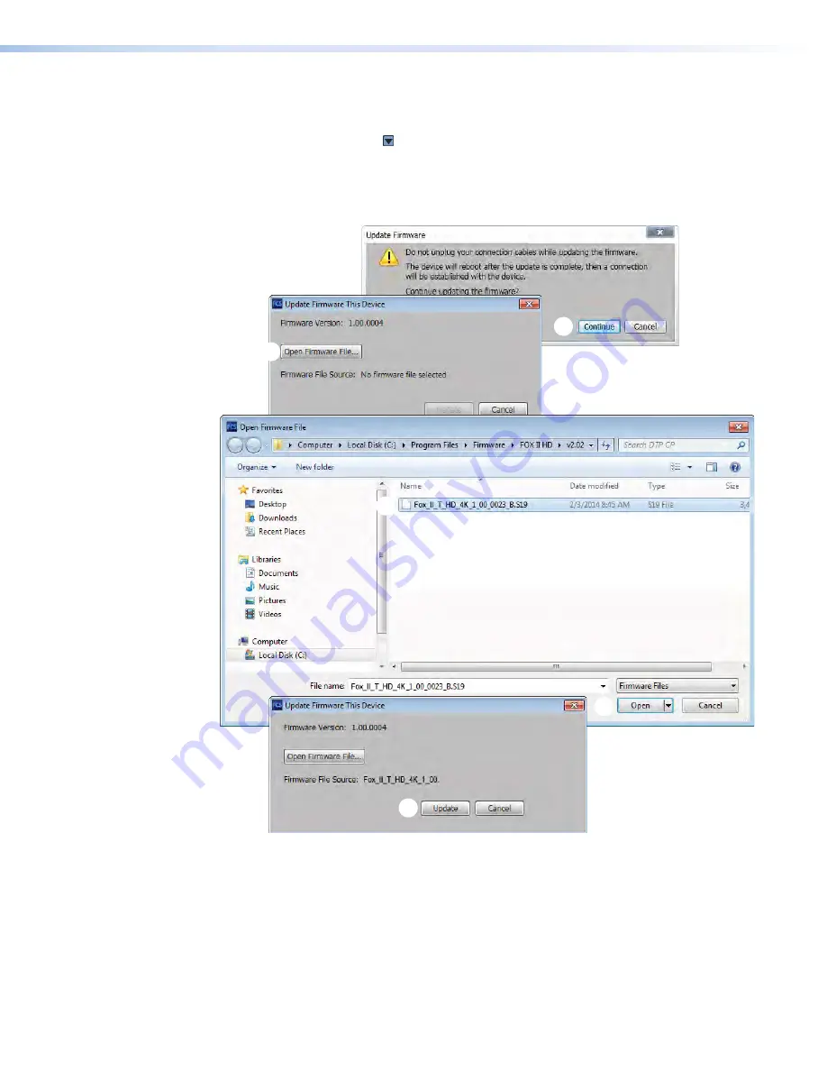
. The software asks you to confirm that 

you want to disconnect it from the unit (see figure 21).

8. 

Click 

Continue

 (

1

). The Product Configuration Software disconnects itself from the unit 

and calls the Firmware Loader utility in the background. The 

Update


Firmware

 dialog 

box appears.


1

1

2

2

3

3

3

3

4

4

Figure 21. 

Updating Firmware

9. 

Click 

Open


Firmware


File

 (

2

). The 

Open

 dialog box opens.

10. 

Navigate to the folder where you saved the firmware upgrade file. Select the file and 
click 

Open

 (

3

). The 

Update


Firmware


This


Device

 dialog box returns to the top.

Summary of Contents for FOX II T HD 4K

Page 1: ...User Guide FOX II T HD 4K Fiber Optic Extenders Fiber Optic Transmitter for HDMI 68 2300 01 Rev B 05 17 ...

Page 2: ...nce importantes qui se trouvent dans la documentation fournie avec le matériel Pour en savoir plus sur les règles de sécurité la conformité à la réglementation la compatibilité EMI EMF l accessibilité et autres sujets connexes lisez les informations de sécurité et de conformité Extron réf 68 290 01 sur le site Extron www extron com Istruzioni di sicurezza Italiano AVVERTENZA Il simbolo se usato su...

Page 3: ... of RGB Systems Inc or Extron Electronics see the current list of trademarks on the Terms of Use page at www extron com Extron Cable Cubby Codec Connect ControlScript CrossPoint DTP eBUS EDID Manager EDID Minder Flat Field FlexOS GlobalViewer Global Configurator Global Scripter Hideaway IP Intercom IP Link Key Minder LinkLicense LockIt MediaLink MediaPort NetPA PlenumVault PoleVault PowerCage PURE...

Page 4: ...ity accessibility and related topics see the Extron Safety and Regulatory Compliance Guide on the Extron website Produit laser de classe 1 Si ce produit a besoin d un quelconque entretient celui ci doit être fait par Extron Electronics et son personnel qualifié ATTENTION L utilisation de commandes la réalisation de réglages ou l exécution de procédures de manière contraire aux dispositions établie...

Page 5: ...les are written in the font shown here Reply from 208 132 180 48 bytes 32 times 2ms TTL 32 C Program Files Extron Variables are written in slanted form as shown here ping xxx xxx xxx xxx t SOH R Data STX Command ETB ETX Selectable items such as menu names menu options buttons tabs and field names are written in the font shown here From the File menu select New Click the OK button Specifications Av...

Page 6: ......

Page 7: ...8 Indications and Operation 11 Front Panel Features 11 Rear Panel Features 12 Operation 13 Remote Control 14 Simple Instruction Set Control 14 Host to Unit Instructions 14 Unit Initiated Messages 15 Error Responses 15 Using the Command and Response Table 16 Product Configuration Software 20 Installing the Software 20 Starting the Program 22 Using the Software 23 Device Menu 27 Updating the Firmwar...

Page 8: ...FOX II T HD 4K Transmitter Contents viii ...

Page 9: ...the fiber optic cables themselves Ne regardez pas dans les connecteurs de câble fibre optique sur le panneau arrière ou dans les câbles fibre optique eux mêmes Plug the attached dust cap into the optical transceiver when the fiber optic cable is unplugged Branchez la protection contre la poussière dans l ensemble émetteur récepteur lorsque le câble fibre optique est débranché About this Guide Abou...

Page 10: ...te Tune r 1 2 3 VCR Lapt op PC DVD Doc Cam Tu ne r On Ch an ne l La st Pre set s Mo re Pre sets 3 2 1 6 5 4 9 8 7 Ent er 0 RS 232 Ethernet Ethernet 4K HDMI 4K DisplayPort to HDMI 4K HDMI Extron SI 28 Surface mount Speakers Extron XPA 1002 Power Amplifier 4K Display RedRay Media Player Local Monitor Up to 30 km 18 75 miles Singlemode Fiber SM Model Audio RS 232 Extron FOX T HD 4K Fiber Optic Transm...

Page 11: ...ay The transmitter has many controls including audio adjustments that are available under RS 232 and USB port SIS control The unit also has video audio fiber light status and lost light alarm indicators The FOX II T HD 4K transmitter is compatible with all Extron FOX II receivers only Fiber Cable Transmission Modes The transmitter is further categorized by the type of fiber optic cable multimode o...

Page 12: ...vice control LED indicators for signal presence HDCP and power Provides a visual indication of system status for real time feedback and monitoring of key performance parameters Loss of light alarms The transmitter has a discrete output that indicates if the link from the receiver has suffered a loss of the light signal Alarm notification for fiber link loss The transmitter can be set up to trigger...

Page 13: ...it on page 32 c Connect the cables and configure the units see Connections c Plug in the power supplies then turn on the display and the input Connections Rear Panel 100 240V 0 5AMAX 50 60 Hz HDMI LOOP THRU L R RS 232 OPTICAL Tx RESET LINK LINK Rx RS 232 IR ALARM Tx Rx G 1 2 L R Tx Rx Tx Rx G AUDIO INPUTS AUDIO RETURN OUT OVER FIBER REMOTE FOX T HD 4K I I A A H H E E G G F F D D B B C C Figure 2 F...

Page 14: ...ER modulated or unmodulated IR signal or both to this 3 5 mm 5 pole captive screw connector for bidirectional RS 232 and IR communication See RS 232 and IR connections on page 9 to wire the connector NOTES If you connect only one fiber optic cable see item H on the next page you will not receive RS 232 or IR reports from the controlled device To receive responses from the controlled device you mus...

Page 15: ...output by the receiver is not HDCP compliant You will not receive RS 232 reports or return audio from the controlled device To receive responses from the controlled device and for HDCP compliance you must install both fiber optic cables 1 Tx required For all one way video audio and serial Transmitter to Receiver OPTICAL Tx LINK LINK Rx OPTICAL Tx LINK LINK Rx 1 1 2 2 communications from the transm...

Page 16: ... first Connection Considerations HDMI connections HDMI signals run at a very high frequency and are prone to errors caused by bad connections or excessive cable length To avoid the loss of an image or jitter follow these guidelines Do not exceed 6 5 feet 2 meters on the input or buffered loop through of the FOX II T HD 4K transmitter Use only the cable specifically designed and intended for high s...

Page 17: ...Tx Rx G 1 2 REMOTE RS 232 IR Tx Rx Tx Rx G OVER FIBER Gnd Tx Rx Figure 4 RS 232 and IR Connector Wiring NOTES The length of exposed wires is important The ideal length is 3 16 inch 5 mm Longer bare wires can short together Shorter wires are not as secure in the connectors and could be pulled out Do not tin the power supply leads before installing them in the connector Tinned wires are not as secur...

Page 18: ...osed wires is important see the RS 232 and IR connector NOTES on page 9 for more information Captive screw output connection See figure 7 to properly wire the captive screw output connector The connector is included with transmitter but you must supply the audio cable Use the supplied tie wrap to strap the audio cable to the extended tail of the connector Unbalanced Stereo Output Balanced Stereo O...

Page 19: ...TIC TRANSMITTER AUDIO EDID HDCP INPUT RETURN OUT FOX T HD 4K A A D D B B C C Figure 9 FOX II T HD 4K Front Panel Features A power indicator Indicates that power is applied to the unit B Video LEDs Signal LED Lights when the transmitter detects an active signal on its video input HDCP LED Lights when the input signal is HDCP encrypted C Audio LEDs Input LED Lights when an analog audio or PCM digita...

Page 20: ...ition Position 2 The EDID is received from the display connected to the receiver NOTE EDID from the display connected to the receiver requires connection of both fiber cables Position 3 The EDID is received from the display connected to the HDMI Loop through connector see item B Position 4 E Specify a resolution The table below identifies the switch positions and the associated resolutions All res...

Page 21: ... products All user files and settings such as audio adjustments and video settings are maintained A mode 1 firmware reset is helpful if a firmware upload was interrupted resulting in a non operational unit A second reset mode resets all settings to their factory defaults except for the current firmware level a mode 5 reset This reset is the same as performed when you issue the EZXXX SIS command se...

Page 22: ... device such as a computer running the HyperTerminal or DataViewer utility or a control system to make remote control of the transmitter possible The protocol for the serial port is as follows 9600 baud no parity 8 data bits 1 stop bit no flow control Simple Instruction Set Control Host to Unit Instructions SIS commands consist of one or more characters per field No special characters are required...

Page 23: ...etected x is the detected resolution such as 1920x1080 60Hz y is the HDCP source status where 0 no source 1 HDCP source 2 non HDCP source a is the rotary switch position 00 through 15 F hex DDC EdidMdrnn The unit sends the EDID Minder change message whenever a change in the position of the front panel DDC hex switch occurs nn is the switch position 0 through 15 F hex HplgO The unit sends the Hot p...

Page 24: ...nabled X Video bit depth 0 auto mode default 1 8 bit X HDCP Mode 0 auto default 1 on X Digital output format 0 auto default 1 DVI 2 HDMI X Audio gain adjustment range 00 to 24 X1 Audio level adjustment range 18 to 24 in 1 dB steps X1 Audio attenuation adjustment range 00 to 18 X1 Audio input format 0 auto default 1 digital embedded HDMI audio 2 analog audio X1 Audio mute 0 mute all 1 mute HDMI 2 m...

Page 25: ...HDCP notification ENHDCP X KEY X EDID resolution See the table below X Value X Value X Value X Value X Value DVI PC values 01 800x600 60 Hz 05 1280x800 60 Hz 09 1400x1050 60 Hz 13 1680x1050 60 Hz 02 1024x768 60 Hz 06 1280x1024 60 Hz 10 1440x900 60 Hz 14 1920x1080 60 Hz 03 1280x720 60 Hz 07 1360x768 60 Hz 11 1600x900 60 Hz 15 1920x1200 60 Hz 04 1280x768 60 Hz 08 1366x768 60 Hz 12 1600x1200 60 Hz 16...

Page 26: ...evel decrement level and show level are not case sensitive Set input audio gain to a dB value X G AudX1 Set the input level to X1 dB gain Example 2G Aud2 Set the input level to 2 dB gain Set input audio attenuation to a dB value X1 g AudX1 Set the input level to X1 dB attenuation Increment input level G AudX1 Increase the audio level by 1 dB Example G Aud3 Increment the input level from 2 dB to 3 ...

Page 27: ... requests Information request I 2LnkX1 SigIX1 ResX2 HdcpIX1 AudIX1 AudOX1 EdidMdrX2 TX The unit responds with the status light detected of the optical Rx link and the digital input signal detected the resolution the HDCP status the input audio selected the signal status of the audio output the EDID rotary switch position and the device type TX Show firmware version Q X2 Example Q 1 23 The factory ...

Page 28: ...oth programs as follows NOTES This procedure uses Internet Explorer Depending on the browser you use some steps or indications may be different Steps 1 through 7 are also used to download firmware update packages 1 Visit the website www extron com and click the Download tab see figure 10 1 OR 1 1 2 2 2 2 3 3 Figure 10 Downloading a Software or Firmware Package 2 Click the Software or Firmware link...

Page 29: ...Run or make a similar confirmation 1 1 1 1 1 1 1 1 1 1 1 Figure 12 Download Warning and Confirmation NOTE Figure 12 may appear different or may not appear at all depending on your Web browser choice and its security settings 7 For a firmware download exit this procedure and return to Updating the Firmware on page 28 8 Follow the on screen instructions The installation creates a C Program Files Ext...

Page 30: ...ation Software Extron Product Configuration Software The Product Configuration Software opens to the Device Discovery window see figure 13 1 1 1 1 1 1 1 1 1 1 2 2 2 2 2 2 2 2 2 2 Figure 13 Device Discovery Screen 2 Select click your FOX II T HD 4K and the USB port see figure 13 1 3 Click Connect 2 The Product Configuration Software opens to the Status window see figure 14 on the next page ...

Page 31: ...ds Indicates the power on the Tx optical module of the unit in dBm 4 Rx Power fields Indicates the power on the Rx optical module of the unit in dBm 5 Operating Temperature Indicates the temperature in degrees Fahrenheit and degrees Celsius 6 Video Signal Presence indicators Indicates green when the transmitter detects a sync signal on its HDMI video input 7 Audio Signal Presence indicators Indica...

Page 32: ... only the Input field 6 and the following is displayed 1 1 4 4 6 6 5 5 3 3 2 2 Figure 15 EDID Minder Screen Click an EDID box in the Available EDID 1 Connected Outputs 2 or Favorites 3 panes to select highlight in yellow the EDID identified by that box If desired drag and drop an EDID box into the Favorites pane If desired reduce the number of EDID boxes displayed by selecting a filter in one of f...

Page 33: ...d setting is useful for video sources that always encrypt their output if the transmitter is HDCP capable If the display connected to the receiver is not HDCP compliant this automatic encryption would result in no display 2 HDCP Mode radio buttons Select the Auto radio button for the transmitter to follow the input video HDCP encryption status on the Loop through connector Select On to always encr...

Page 34: ...o select among 720p and 1080p color bars for the transmitter to send to the receiver on the fiber cable Or select Off to transmit the digital video that is input on the HDMI input port 8 Audio Format radio buttons Auto Detect radio button Transmit the embedded digital audio if detected otherwise transmit analog audio HDMI radio button Transmit the embedded digital audio Analog radio button Transmi...

Page 35: ... or reset to the default value by clicking the Device Name tab opening the Device Name dialog box see figure 18 The Apply button becomes selectable when you have entered a name in the Enter a device name field Figure 18 Device Name Dialog Box Reset Device Opens a dialog box see figure 19 that allows you to reset the transmitter Reset returns all settings to their default values Figure 19 Reset Dev...

Page 36: ...Click Finish 2 The program extracts the firmware files and places them in a folder identified in the InstallShield Wizard ATTENTION The firmware file must have an s19 extension Other file types can cause the transmitter to stop functioning Le firmware doit avoir une extension S19 D autres types de fichiers peuvent nuire au fonctionnement de l émetteur NOTES Note the folder to which the firmware fi...

Page 37: ...FOX II T HD 4K Transmitter Remote Control 29 Folder where firmware is installed Sample location only 1 1 1 1 2 2 3 3 Figure 20 Downloading Firmware Upgrade Files ...

Page 38: ...nit see figure 21 8 Click Continue 1 The Product Configuration Software disconnects itself from the unit and calls the Firmware Loader utility in the background The Update Firmware dialog box appears 1 1 2 2 3 3 3 3 4 4 Figure 21 Updating Firmware 9 Click Open Firmware File 2 The Open dialog box opens 10 Navigate to the folder where you saved the firmware upgrade file Select the file and click Ope...

Page 39: ...e connection installs the update and then verifies the firmware At the conclusion of the process the utility reports Update Complete and prompts you to reconnect to the device see figure 20 1 1 Figure 22 Reconnect Message 13 Click Close 1 The Product Configuration Software window returns to the front showing the Device Discovery window see figure 13 on page 22 14 Reconnect the program as described...

Page 40: ... closed or multi unit rack assembly the operating ambient temperature of the rack environment may be greater than room ambient Therefore consider installing the equipment in an environment compatible with the 122 F 50 C maximum ambient temperature Tma specified by Extron Reduced air flow Installation of the equipment in a rack should be such that the amount of air flow required for safe operation ...

Page 41: ... Europe and Africa Extron Europe Hanzeboulevard 10 3825 PH Amersfoort The Netherlands China Extron China 686 Ronghua Road Songjiang District Shanghai 201611 China Asia Extron Asia Pte Ltd 135 Joo Seng Road 04 01 PM Industrial Bldg Singapore 368363 Singapore Middle East Extron Middle East Dubai Airport Free Zone F13 PO Box 293666 United Arab Emirates Dubai This Limited Warranty does not apply if th...

Reviews: