


- 46 -
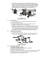
For Ogura clutches proceed with the following steps:
a)
Stop engine and remove key.
b)
Engage parking brake.
c)
Place .012-.024 inch feeler gages through each of the three clutch gap
holes. If gap exceeds this range, tighten the three adjusting nuts until the
proper gap is obtained (See Fig.16). The three clutch gap holes are
located at the “nut side” of the adjusting bolts. The adjusting bolts can be
identified by the springs surrounding each bolt.
FIG. 16
CLUTCH GAP ADJUSTMENT
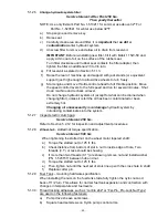
5.2.13
Reverse Indicator Adjustment:
a)
Stop engine and remove ignition key.
b)
Tilt seat forward.
c)
Begin with either the left or right motion control lever. Move lever to the
neutral position and pull lever back until the clevis pin (on arm below pivot
shaft) contacts the end of the slot (just beginning to put pressure on
spring), See Fig 17.
d)
Check where lever is relative to notch in console (should be centered
allowing lever to pivot outward to the neutral lock position).
e) If adjustment is needed, loosen the nut against the yoke and while applying
slight rearward pressure on the motion control lever, turn the head of the
adjustment bolt in the appropriate direction until lever is centered (keeping
rearward pressure on the lever will keep the pin at the end of the slot and
allow the adjustment bolt to move the lever to the appropriate position).
Tighten lock nut.
f)
Repeat on opposite side of unit.
5.2.14
Motion control linkage adjustment.
WARNING
POTENTIAL HAZARD
♦
Engine must be running and drive wheels must be
turning so motion control adjustment can be performed.
WHAT CAN HAPPEN
♦
Contact with moving parts or hot surfaces may cause
personal injury.
HOW TO AVOID THE HAZARD
♦
Keep fingers, hands, and clothing clear of rotating
components and hot surfaces.
Summary of Contents for Laser Z LZ18KC523
Page 1: ......
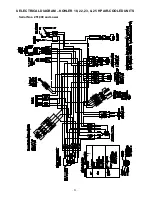
Page 57: ... 52 8 ELECTRICAL DIAGRAM KOHLER 18 22 23 25 HP AIR COOLED UNITS Serial Nos 251 999 and Lower ...
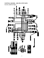
Page 58: ... 53 ELECTRICAL DIAGRAM KOHLER 23 25 HP AIR COOLED UNITS Serial Nos 252 000 and Higher ...
Page 59: ... 54 ELECTRICAL DIAGRAM 22 23 HP KAWASAKI LIQUID COOLED UNITS ...
Page 60: ... 55 ELECTRICAL DIAGRAM KOHLER 26 HP EFI UNITS Serial Nos 251 999 and Lower ...
Page 61: ... 56 ELECTRICAL DIAGRAM KOHLER 26 HP EFI UNITS Serial Nos 252 000 and Higher ...
Page 62: ... 57 ELECTRICAL DIAGRAM 23 HP KAWASAKI AIR COOLED ...
Page 63: ... 58 ELECTRICAL DIAGRAM 27 HP KAWASAKI LIQUID COOLED ...
Page 64: ... 59 9 HYDRAULIC DIAGRAM ...
Page 67: ... 62 NOTES ...
Page 68: ... 63 SERVICE RECORD Date Description of Work Done Service Done By ...
Page 69: ... 64 ...


