- 16 -
3.2.2
Check the voltage of the battery with a digital voltmeter. Locate the voltage reading
of the battery in the table below and charge the battery for the recommended time
interval to bring the charge up to a full charge of 12.6 volts or greater.
IMPORTANT:
Make sure the negative battery cables are disconnected and the
battery charger used for charging the battery has an output of 16 volts and 7
amps or less to avoid damaging the battery (see chart below for recommended
charger settings).
Voltage
Reading
Percent
Charge
Maximum
Charger Settings
Charging Interval
12.6 or greater
100%
16 volts/7 amps
No Charging Required
12.4 – 12.6
75 – 100%
16 volts/7 amps
30 Minutes
12.2 – 12.4
50 – 75%
16 volts/7 amps
1 Hour
12.0 – 12.2
25 – 50%
14.4 volts/4 amps
2 Hours
11.7 – 12.0
0 – 25%
14.4 volts/4 amps
3 Hours
11.7 or less
0%
14.4 volts/2 amps
6 Hours or More
CAUTION
POTENTIAL HAZARD
♦
If the ignition is in the “ON” position there is potential
for sparks and engagement of components.
WHAT CAN HAPPEN
♦
Sparks could cause an explosion or moving parts
could accidentally engage causing personal injury.
HOW TO AVOID THE HAZARD
♦
Be sure ignition switch is in the “OFF” position before
charging the battery.
3.2.3
Connect the negative battery cables.
NOTE:
If the positive cable is also disconnected, connect the
positive (red)
cable and the red wire
to the positive terminal on the battery
first,
then connect
the negative (black) cable and white/white wire to the negative terminal on the
battery (red wire and white/white wire are only on some units). Slip insulator boot
over the positive terminal.
NOTE:
If time does not permit charging the battery, or if charging equipment is
not available, connect the negative battery cables and run the vehicle
continuously for 20 to 30 minutes to sufficiently charge the battery.
For Serial Nos. 251,999 and lower.
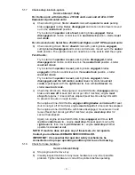
The machine is shipped with a dry battery
.
3.2.4
Remove battery from machine. Tilt seat up to gain access to the battery.
Disconnect
battery cables –
negative (black) cable first
. Remove battery
hold-down and lift battery out.
Summary of Contents for Laser Z LZ18KC523
Page 1: ......
Page 57: ... 52 8 ELECTRICAL DIAGRAM KOHLER 18 22 23 25 HP AIR COOLED UNITS Serial Nos 251 999 and Lower ...
Page 58: ... 53 ELECTRICAL DIAGRAM KOHLER 23 25 HP AIR COOLED UNITS Serial Nos 252 000 and Higher ...
Page 59: ... 54 ELECTRICAL DIAGRAM 22 23 HP KAWASAKI LIQUID COOLED UNITS ...
Page 60: ... 55 ELECTRICAL DIAGRAM KOHLER 26 HP EFI UNITS Serial Nos 251 999 and Lower ...
Page 61: ... 56 ELECTRICAL DIAGRAM KOHLER 26 HP EFI UNITS Serial Nos 252 000 and Higher ...
Page 62: ... 57 ELECTRICAL DIAGRAM 23 HP KAWASAKI AIR COOLED ...
Page 63: ... 58 ELECTRICAL DIAGRAM 27 HP KAWASAKI LIQUID COOLED ...
Page 64: ... 59 9 HYDRAULIC DIAGRAM ...
Page 67: ... 62 NOTES ...
Page 68: ... 63 SERVICE RECORD Date Description of Work Done Service Done By ...
Page 69: ... 64 ...


