background image

- 11 -

2. SPECIFICATIONS

2.1 MODEL NUMBER:

2.2 ENGINE:

2.2.1 

Engine Specifications: See your Engine Owner’s Manual

2.2.2

RPM: 18, 22, 23, & 25 HP Kohler


 and 22 HP Kawasaki Liquid-cooled models

Full Speed: 3600 RPM (No Load)    Idle:1500 RPM

26 HP EFI Kohler and 23 HP Kawasaki Liquid-cooled models
Full Speed: 3750 RPM (No Load)    Idle:1500 RPM
27 HP Kawasaki Liquid-cooled models
Full Speed: 3750 RPM (No Load)    Idle: 2200 RPM

2.3 FUEL SYSTEM

2.3.1

Capacity: 


9.0 gal. (34 L.) for Serial Nos. 160,000-189,999

      11.0 gal. (42 L.) for Serial Nos. 190,000 & Higher

2.3.2

Type of Fuel:  Regular 

unleaded

 gasoline, 87 octane or higher

2.3.3

Fuel Filter: 

Kohler Air-cooled units: In-line 15 Micron 

Kohler

 P/N 2405002.

Kohler 26 HP EFI units: In-line 22 Micron Exmark P/N 99-9403 (low pressure).

      In-line 10 Micron 

Kohler

 P/N 2405003 (high pressure).

Kawasaki Liquid-cooled units: In-line 40 Micron 

Kawasaki

 P/N 49019-1055

Kawasaki Air-cooled units: In-line 

Kawasaki

 P/N 49019-7001

2.3.4

Fuel Shut-Off Valve: 1/4 turn increments (left tank, “OFF”, right tank)


2.4 ELECTRICAL SYSTEM

2.4.1

Charging System: All Kohler & Kawasaki Air-cooled units - Flywheel Alternator


Kawasaki 22 & 23 HP Liquid-cooled units - External Alternator
Kawasaki 27 HP Liquid-cooled units – 3 Phase Flywheel Alternator

2.4.2

Charging Capacity: All Kohler & Kawasaki Air-cooled units - 15 amps

Kawasaki 22 & 23 HP Liquid-cooled units – 37 amps
Kawasaki 27 HP Liquid-cooled units – 30 amps

2.4.3

Battery Type:  BCI Group U1

2.4.4

Battery Voltage:  12 Volt

2.4.5

Polarity:  Negative Ground

2.4.6 

Fuses:  Kohler Air-cooled units –Two 20 amp blade type

             Kohler 26 HP EFI units – Two 20 amp and one 10 amp blade type

Kawasaki 22, 23, & 27 HP Liquid-cooled units – One 20 amp and two 30

amp blade type

Serial Nos. 160,000 – 189,999

LZ18KC523; LZ22KC523; LZ25KC523; LZ22KC603; LZ25KC603

Serial Nos. 190,000 – 219,999

LZ18KC523; LZ22KC523; LZ22LKA523; LZ23KC523; LZ25KC523; LZ22KC604;
LZ22LKA604; LZ23KC604; LZ25KC604; LZ26KC604; LZ25KC724; LZ26KC724

Serial Nos. 220,000 – 259,999

LZ22LKA523;


LZ23KC523;


LZ25KC523;


LZ22LKA604; LZ23KC604; LZ25KC604;

LZ26KC604; LZ23LKA604;


LZ25KC724; LZ26KC724

Serial Nos. 260,000 and Higher

LZ25KC524; LZ23LKA524; LZ23KA604; LZ23KC604; LZ25KC604; LZ26KC604;
LZ23LKA604; LZ26KC724; LZ27LKA604; LZ27LKA724

Summary of Contents for Laser Z LZ18KC523

Page 1: ......

Page 2: ...owed Long term exposure to vapors has caused cancer in laboratory animals WHAT CAN HAPPEN Failure to use caution may cause serious injury or illness HOW TO AVOID THE HAZARD Avoid prolonged breathing of vapors Keep face away from nozzle and gas tank container opening Keep away from eyes and skin Never siphon by mouth IMPORTANT When the mower is used or operated on any California forest brush or gra...

Page 3: ...bmitting the Exmark Parts Plus order to Exmark by 3 00 p m central time the Distributor pays for the part and freight 3 Exmark being unable to ship the part and the Exmark parts order is received by 3 00 p m central time Exmark pays for the part and freight 4 If the part does not arrive overnight due to the shipper UPS the shipper pays for the freight and Exmark pays for the part The following res...

Page 4: ...wer maintain its maximum efficiency and promote safe operation If additional information is needed or should you require trained mechanic service contact your authorized Exmark equipment dealer or distributor All Exmark equipment dealers and distributors are kept informed of the latest methods of servicing and are equipped to provide prompt and efficient service in the field or at their service st...

Page 5: ...ck Tire Pressure 18 3 5 Install Seat Retaining Rod Standard Seat or Seat Suspension Seat 18 3 6 Install Foot Lift Assist Kohler 26 HP EFI Only 19 3 7 Install Canister Air Cleaner Kohler 26 HP EFI Only 19 3 8 Install Motion Control Levers 20 3 9 Position Discharge Chute 20 3 10 Service Engine 20 3 11 Service Engine Coolant 20 21 3 12 Service Hydraulic Oil 21 4 OPERATION INSTRUCTIONS 4 1 Controls 21...

Page 6: ...te this unit 1 2 2 Read the instructions carefully Familiarize yourself with the controls and the proper use of the equipment 1 2 3 Never allow children teenagers or people unfamiliar with these instructions to use the mower 1 2 4 Avoid mowing while people especially children or pets are nearby Keep in mind that the operator or user is responsible for accidents or hazards occurring to other people...

Page 7: ...O AVOID THE HAZARD DO NOT smoke while refueling and stay away from an open flame or where gasoline fumes may be ignited by spark Refuel only in a well ventilated area or refuel outdoors Store gasoline in an approved container and keep it out of the reach of children Add fuel before starting the engine Never remove the cap of the fuel tank or add fuel when engine is running or when the engine is ho...

Page 8: ...ble then refuel such equipment on a truck or trailer from a portable container rather than from a gasoline dispenser nozzle If a gasoline dispenser nozzle must be used keep the nozzle in contact with the rim of the fuel tank or container opening at all times until fueling is complete WARNING POTENTIAL HAZARD Gasoline vapor can collect inside enclosed trailers and may be ignited by electrical spark...

Page 9: ...ng parts can cause traumatic amputation or severe lacerations HOW TO AVOID THE HAZARD Operate equipment with all guards in place Keep hands feet hair jewelry or clothing away from rotating parts 1 4 1 Give complete undivided attention to the job at hand 1 4 2 Mow only in daylight or good artificial light NEVER carry passengers DO NOT operate the mower when children or others are in the area 1 4 3 ...

Page 10: ...f the fuel When the machine will not be used for a few days During transport to and from the job When parked inside a building 1 4 15 This mower was designed for one operator only Keep all others away from mower during operation 1 4 16 Do Not mow without the discharge chute in place 1 4 17 If jump starting is required a connect the positive power cable from the positive post on the booster battery...

Page 11: ...escaping under pressure can penetrate skin and cause injury WHAT CAN HAPPEN Fluid accidentally injected into the skin must be surgically removed within a few hours by a doctor familiar with this form of injury or gangrene may result HOW TO AVOID THE HAZARD Make sure all hydraulic fluid hoses and lines are in good condition an all hydraulic connections and fittings are tight before applying pressur...

Page 12: ...ible Remove all grease dirt and debris from safety signs and instructional labels 1 6 2 Safety signs must be replaced if they are missing or illegible 1 6 3 When new components are installed be sure that current safety signs are affixed to the replaced components 1 6 4 New safety signs may be obtained from your authorized Exmark equipment dealer or distributor or from Exmark Mfg Co Inc 1 6 5 Safet...

Page 13: ...N LH Side of Cutting Height Adjustment Plate PART NO 1 403005 LOCATION Left and Right Corners of Mower Deck PART NO 65 2690 LOCATION Top of Radiator Trim Plate LH RH Sides Serial Nos 220 000 and Higher PART NO 1 643401 LOCATION On Tilt Switch Serial Nos 220 000 thru 251 999 PART NO 1 643372 LOCATION Top LH Side of Console Under Front of Seat PART NO 103 1077 LOCATION Top LH Side of Mower Deck next...

Page 14: ...0 LOCATION Left Rear Corner Top of Mower Deck PART NO 1 513742 LOCATION Top of Mower Deck Belt Shields Left and Right Sides PART NO 1 633922 LOCATION Front Center on Top of Mower Deck PART NO 1 523552 LOCATION Top of Hydraulic Reservoir Under the Seat Kawasaki Liquid Cooled Units Only PART NO 1 643253 LOCATION LH and RH Sides of Radiator Mount Plate Kohler 26 HP EFI Units Only PART NO 1 643288 LOC...

Page 15: ... Top LH Side of Mower Deck Frame PART NO 1 303508 LOCATION RH Side on Top Rear of Mower Deck PART NO 1 643339 LOCATION Top of Right Engine Baffle PART NO 1 633702 LOCATION Bottom Side of Floor Pan Serial Nos 251 999 and Lower PART NO 1 513929 LOCATION Hydraulic Reservoir Mounting Bracket Under the Seat Serial Nos 252 000 and Higher PART NO 103 0245 LOCATION Top of console ...

Page 16: ...OFF right tank 2 4 ELECTRICAL SYSTEM 2 4 1 Charging System All Kohler Kawasaki Air cooled units Flywheel Alternator Kawasaki 22 23 HP Liquid cooled units External Alternator Kawasaki 27 HP Liquid cooled units 3 Phase Flywheel Alternator 2 4 2 Charging Capacity All Kohler Kawasaki Air cooled units 15 amps Kawasaki 22 23 HP Liquid cooled units 37 amps Kawasaki 27 HP Liquid cooled units 30 amps 2 4 3...

Page 17: ...saki 23 27HP Liquid cooled 50 50 mix of DexCool extended life antifreeze and water 2 5 3 Coolant Capacity 4 quarts 2 6 OPERATOR CONTROLS 2 6 1 Steering and Motion Control Separate levers on each side of the console control speed and direction of travel of the respective drive wheels Steering is controlled by varying the position of the levers relative to each other Moving motion control levers out...

Page 18: ... km hr forward 0 9 4 mph 15 1 km hr forward 0 4 2 mph 6 8 km hr reverse 0 6 0 mph 9 7 km hr reverse 26 HP Kohler EFI and 23 27 HP Kawasaki Liquid cooled models 0 9 8 mph 15 8 km hr forward 0 6 3 mph 10 1 km hr reverse 2 8 7 Drive wheel release valves allow machine to be moved when engine is not running 2 9 TIRES AND WHEELS 2 9 1 Tires Drive Front Cstr Qty 2 2 Ply 4 4 Infl 13 psi 90 kPa 13 psi 90 k...

Page 19: ... assist lever to aid in raising the deck The deck lift assist lever is an optional accessory for all other units 2 10 8 Mulching Kit Optional 2 11 Dimensions 2 11 1 Overall Width without deck deflector up deflector down Serial Nos 160 000 259 999 w 52 Deck 49 8 in 126 5 cm 53 4 in 135 6 cm 63 1 in 160 3 cm Serial Nos 260 000 Higher w 52 Deck 49 8 in 126 5 cm 53 4 in 135 6 cm 64 2 in 163 1 cm Seria...

Page 20: ... ft lbs Anti Scalp Roller Bolts 40 45 ft lbs Engine Mounting Bolts Kohler 30 35 ft lbs Engine Mounting Bolts Kawasaki 25 30 ft lbs Wheel Lug Nuts 90 95 ft lbs Wheel Motor Mounting Bolts 72 77 ft lbs Wheel Hub Slotted Nut minimum125 ft lbs 3 ASSEMBLY INSTRUCTIONS 3 1 UNCRATE MOWER 3 2 SERVICE BATTERY For Serial Nos 252 000 and higher The machine is shipped with a filled lead acid battery 3 2 1 Tilt...

Page 21: ...potential for sparks and engagement of components WHAT CAN HAPPEN Sparks could cause an explosion or moving parts could accidentally engage causing personal injury HOW TO AVOID THE HAZARD Be sure ignition switch is in the OFF position before charging the battery 3 2 3 Connect the negative battery cables NOTE If the positive cable is also disconnected connect the positive red cable and the red wire...

Page 22: ...lames or cigarettes away from battery Ventilate when charging or using battery in an enclosed space Make sure venting path of battery is always open once battery is filled with acid 3 2 6 Fill cells with battery grade sulfuric acid 1 265 specific gravity to halfway between top of separators and bottom of vent well 3 2 7 Let battery stand for 1 2 hour after filling If battery acid level has fallen ...

Page 23: ...r models have studs installed in the wheel hub and require wheel nuts 3 4 CHECK TIRE PRESSURE 3 4 1 Check tire pressure in caster and drive tires Proper inflation pressure for all four 4 tires is 13 psi 90 kPa Adjust if necessary 3 5 INSTALL SEAT RETAINING ROD Standard Seat or SEAT Suspension Seat 3 5 1 For all units with a standard seat Tilt seat up Remove 5 16 nyloc nut from bolt attaching seat ...

Page 24: ... holes with top holes in the valve covers Reinstall valve cover screws through air cleaner bracket and torque to 70 in lb 4 9 N m d Remove plastic plugs from air intake elbow on engine and air cleaner hose Adjust the air cleaner and hose as required and connect intake hose to air cleaner outlet Position and tighten the two hose clamps to secure the hose connections e Secure air cleaner by tighteni...

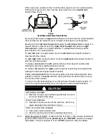
Page 25: ...osition See Fig 5 loosen the hardware and make the appropriate adjustment by sliding tilting the lever s forward or backward until properly aligned and tighten hardware FIG 4 FIG 5 CONTROL ARM SHAFT LEVER ALIGNMENT b If the ends of the levers hit against each other while in the drive position levers rotated in as far as possible make adjustments by moving the levers outwards to the neutral lock po...

Page 26: ...ne as required to bring the level up to the indicator line on the bottle NOTE Kawasaki 23 27 HP Liquid cooled units should only be filled with Dex Cool extended life coolant Dex Cool extended life coolant can be identified by its orange color 3 12 SERVICE HYDRAULIC OIL The machine is shipped with hydraulic oil filled to the top the baffle in the reservoir Run the machine for approximately 15 minut...

Page 27: ...r back beyond neutral while holding the right lever slightly ahead of neutral To make a zero turn to the right pull the right lever back beyond neutral while holding the left lever slightly ahead of neutral Pulling the levers back from the neutral position will cause the respective drive wheels to rotate in a reverse direction spring tension can be felt when moving into reverse from neutral To tur...

Page 28: ...be in seat with brake engaged motion control levers out neutral lock position and blade engagement switch OFF to start engine For Air cooled units Serial Nos 252 000 and Higher and 27 HP Kawasaki Liquid cooled units Brake must be engaged motion control levers out neutral lock position and blade engagement switch OFF to start engine It is not necessary for the operator to be in the seat to start th...

Page 29: ...or fuel priming air purging instructions 4 2 2 Make sure you understand the controls their locations their functions and their safety requirements 4 2 3 Refer to Maintenance Section 5 and perform all the necessary inspection and maintenance steps 4 3 MOWING 4 3 1 Open fuel shut off valve left or right tank 4 3 2 Starting Engine For Kohler units Serial Nos 251 999 and Lower and 22 23 HP Kawasaki Li...

Page 30: ...um of 15 seconds then stop the engine Rotate ignition switch to OFF position Remove the key to prevent children or other unauthorized persons from starting engine Close fuel shut off valve when machine will not be used for a few days when transporting and when the unit is parked inside a building 4 4 TRANSPORTING 4 4 1 Transporting a Unit Use a heavy duty trailer or truck to transport the machine ...

Page 31: ... unit up a ramp to avoid tipping backward Avoid sudden deceleration while backing unit down a ramp to avoid tipping backward WARNING POTENTIAL HAZARD Gasoline vapor can collect inside enclosed trailers and may be ignited by electrical sparks or hot engine exhaust components WHAT CAN HAPPEN Explosion and fire may occur resulting in property damage personal injury and or death HOW TO AVOID THE HAZAR...

Page 32: ...maneuvers can cause the unit to tip backward 5 MAINTENANCE ADJUSTMENTS 5 1 PERIODIC MAINTENANCE 5 1 1 Check engine oil level Service Interval Daily a Make sure engine is stopped and on a level surface b For Kawasaki Liquid Cooled units tilt seat up and tilt hood forward to gain access to the engine area c Check with engine cold d Clean area around dipstick Remove dipstick and wipe oil off Reinsert...

Page 33: ... to 12 4 volts Note To prevent damage due to freezing battery should be fully charged before putting away for winter storage a Check the voltage of the battery with a digital voltmeter Locate the voltage reading of the battery in the table below and charge the battery for the recommended time interval to bring the charge up to a full charge of 12 6 volts or greater IMPORTANT Make sure the negative...

Page 34: ... in engine cover Rotate engine cover forward and wipe debris from radiator core as required Inspect seals in engine cover and replace as necessary 5 1 5 Clean grass build up under deck Service Interval Daily a Stop engine and remove key b Raise deck to the transport 5 cutting height position Lift the front of unit and support unit using jack stands or equivalent support CAUTION POTENTIAL HAZARD Ra...

Page 35: ...ng a mower deck with loose or weakened blade bolts can be dangerous WHAT CAN HAPPEN A loose or weakened blade bolt could allow a blade rotating at a high speed to come out from under the deck causing serious injury or property damage HOW TO AVOID THE HAZARD Replace the blade bolt after striking a foreign object Use only the following replacement parts 52 60 decks Serial Nos 259 999 lower Blade bol...

Page 36: ...the left motion control lever in starter must not crank repeat again with the right lever in then with both levers in starter must not crank c Check the kill circuits Run engine at one third throttle disengage parking brake and raise off of seat but do not get off of machine engine must stop after approx 1 2 second has elapsed seat has time delay kill switch to prevent cut outs on rough terrain Ru...

Page 37: ...e air cleaner c Loosen retaining clips and remove air cleaner compartment cover d Check paper element Gently tap the paper element to dislodge any dirt DO NOT wash or use pressurized air to clean paper element Replace if dirty bent or damaged e Reinstall paper element Position the cover so that the rubber dust ejector is pointing downward and secure with retaining clips 5 1 10 Check Spark Arrester...

Page 38: ...er apply a thin coating of oil on the surface of the rubber seal Turn filter clockwise until rubber seal contacts the filter adapter then tighten filter an additional 2 3 to 3 4 turn f Clean around oil fill cap and remove cap Fill to specified capacity and replace cap Use oil recommended in engine owner s manual DO NOT overfill g Start the engine and check for leaks 5 1 12 Change engine coolant Ka...

Page 39: ...e located in either cylinder wall adjacent to the main engine block The plugs may be identified as hex head bolts with a black finish See Figure 8 For 27 HP Kawasaki Liquid Cooled units The plug may be accessed from the bottom left hand side of the engine The plug may be identified as a hex head bolt with a black finish See Figure 8 FIG 8 COOLANT PLUG LOCATION a Re install all drain plugs and hose...

Page 40: ...radiator cap Make sure that the cap is completely seated by pressing down firmly while turning until the cap stops Once the cap is installed the engine may be stopped 5 1 13 Check hydraulic oil level Service Interval 40 hr a Stop engine b Tilt seat up c Clean area around hydraulic reservoir cap and remove cap Oil level should be to the top of the baffle inside the tank If not add oil Use only Mobi...

Page 41: ... See Sections 5 2 3 through 5 2 6 for belt adjustment 5 1 16 Lubricate grease fittings Service Interval Refer to chart a Stop engine and remove key b Lubricate fittings with one to two pumps of NGLI grade 2 multi purpose gun grease Refer to the following chart for fitting locations and lubrication schedule LUBRICATION CHART FITTING LOCATIONS INITIAL PUMPS NO of PLACES SERVICE INTERVAL 1 Front Cast...

Page 42: ...With open end of wheel up fill area inside wheel around caster spacer with NGLI grade 2 multi purpose gun grease h Insert the second 1 bearing 1 new seal and 1 bearing spacer i Put wheel and tire assembly on the unit and adjust by tightening the nyloc nut until wheel will not turn freely Back nut off 1 6 of a turn so the wheel will just turn with a slight amount of drag IMPORTANT To prevent seal a...

Page 43: ...cause improper cooling c Make sure cooling shrouds are reinstalled Operating the engine without cooling shrouds will cause engine damage due to overheating 5 1 23 Check spark plugs Service Interval 160 hrs a Remove spark plugs check condition and reset gaps or replace with new plugs See Engine Owners Manual 5 1 24 Change fuel filter Service Interval As Required a A fuel filter is installed between...

Page 44: ...r pressure gauge with an integral relief valve Kohler Part No 2445504 is recommended for relieving pressure and purging air in the fuel system To relieve the system of pressure a Stop engine and remove key b Allow the engine to cool completely c Connect the black tester hose from the Kohler pressure gauge to the test valve in the fuel rail d Route the clear hose into a portable gasoline container ...

Page 45: ...rained when changing filter unless it is felt the oil has been contaminated or been extremely hot Changing oil unnecessarily could damage hydraulic system by introducing contaminates into the system 5 1 27 Inspect electric clutch gap Service Interval 250 hrs Refer to Section 5 2 12 for inspection and adjustment procedures 5 1 28 Wheel hub slotted nut torque specification Service Interval 500 hrs W...

Page 46: ...ng or making any adjustments to the unit 5 2 1 Cutting Height Adjustment a Stop machine and move drive levers out to neutral lock position b Disengage blades c Raise the deck lever to the transport position also the 5 cutting height position See Fig 9 For Kohler 26 HP EFI units and all 72 units the deck can be raised by pulling the deck lever up and or by pushing on the deck lift assist lever NOTE...

Page 47: ...rest at the 1 1 2 height position Place locking pliers between the rear swivel and spring stop to hold the deck in this position See Fig 11 g Place a 3 4 thick block of wood under each of the two 2 rear anti scalp roller brackets and place one under one of the front center anti scalp roller brackets h Loosen the four 4 top chain bolts in slots Check the length of the rod swivel assemblies The dist...

Page 48: ...elt Tension Adjustment Self tensioning idler adjust as follows a Stop engine and remove key b Check to make sure the center of the bolt head in the center of the spring loaded pulley on left side engine deck support is positioned between the centers of the two alignment holes in the left support plate See Fig 12 It is necessary to adjust the belt tension when the center of the bolt head is at or b...

Page 49: ...pped with a time delayed seat switch When the operator raises off the seat with either the brake disengaged or the cutting blades engaged the engine should stop after 1 2 second has elapsed b To adjust seat switch loosen locknut on bottom of the actuator rod 5 16 x 7 bolt and adjust the nuts to move the actuator plate up or down on the rod 5 2 8 Belt Guide Adjustment a Stop engine and remove key b...

Page 50: ...osen the nut directly below the yoke Turn the bottom nut below washer until the correct measurement is obtained See Fig 14 turn nut clockwise to lengthen the gap screws rod into yoke and turn counter clockwise to shorten the gap screws rod out of yoke Tighten nut against yoke and check opposite side of unit repeat if necessary 5 2 11 Adjust Throttle Lever Tension a Stop engine and remove key b Ten...

Page 51: ...beginning to put pressure on spring See Fig 17 d Check where lever is relative to notch in console should be centered allowing lever to pivot outward to the neutral lock position e If adjustment is needed loosen the nut against the yoke and while applying slight rearward pressure on the motion control lever turn the head of the adjustment bolt in the appropriate direction until lever is centered k...

Page 52: ...seat forward e Loosen locknuts from the ball joints on the two rods which connect the motion control assemblies to the pump control arms See Fig 17 NOTE The nuts to the front the unit on each rod have left hand threads FIG 17 MOTION CONTROL ADJUSTMENT f Start engine Brake must be engaged and motion control levers out to start engine Operator does not have to be in the seat because of the jumper wi...

Page 53: ...rest on seat Locate square tab marked with the numbers 1 through 4 Rotate square tab 1 4 turn to raise or lower the armrest in approximately 1 4 increments See Fig 19 FIG 19 ARMREST ADJUSTMENT 6 WASTE DISPOSAL 6 1 MOTOR OIL DISPOSAL Engine oil and hydraulic oil are both pollutants to the environment Dispose of used oil at a certified recycling center or according to your state and local regulation...

Page 54: ...cury and will apply sound disposal practices when these devices reach their normal end of life or are damaged Several states have passed laws concerning the disposal of devices containing mercury In all the remaining states it is advisable to follow similar procedures The laws state that these sealed devices contain mercury and should not be placed in the garbage until the mercury is removed and r...

Page 55: ...he mower deck will be approximately 1 4 lower than the back of the mower deck This is the rake of the deck d Check blades tip to tip for straightness they should be within 3 16 or one blade width from being in line 7 3 ENGINE WILL NOT START a Make sure the battery has a full charge See section 5 1 3 for charging instructions b For all units except Kohler 26 HP EFI Be sure the throttle control is m...

Page 56: ...EVEL DIRTY AIR SCREEN INSUFFICIENT BATTERY CHARGE Will not start X X X X X X X Hard starting X X X X X X X Stops suddenly X X X X X X X Lacks power X X X X X X X X Operates erratically X X X X X X X Knocks or pings X X X Skips or misfires X X X X X Backfires X X X X X Overheats X X X X X High fuel consumption X X X X On Kawasaki Liquid Cooled units check for dirty radiator core 7 4 ENGINE ERROR CO...

Page 57: ... 52 8 ELECTRICAL DIAGRAM KOHLER 18 22 23 25 HP AIR COOLED UNITS Serial Nos 251 999 and Lower ...

Page 58: ... 53 ELECTRICAL DIAGRAM KOHLER 23 25 HP AIR COOLED UNITS Serial Nos 252 000 and Higher ...

Page 59: ... 54 ELECTRICAL DIAGRAM 22 23 HP KAWASAKI LIQUID COOLED UNITS ...

Page 60: ... 55 ELECTRICAL DIAGRAM KOHLER 26 HP EFI UNITS Serial Nos 251 999 and Lower ...

Page 61: ... 56 ELECTRICAL DIAGRAM KOHLER 26 HP EFI UNITS Serial Nos 252 000 and Higher ...

Page 62: ... 57 ELECTRICAL DIAGRAM 23 HP KAWASAKI AIR COOLED ...

Page 63: ... 58 ELECTRICAL DIAGRAM 27 HP KAWASAKI LIQUID COOLED ...

Page 64: ... 59 9 HYDRAULIC DIAGRAM ...

Page 65: ...nse of delivering the mower to the dealer for warranty work nor the expense of returning it back to the owner after repair or replacement Our responsibility in respect to claims is limited to making the required repairs or replacements and no claim of breach of warranty shall be cause for cancellation or rescission of the contract of sale of any Exmark mower Proof of purchase may be required by th...

Page 66: ...charges or travel charges vi loss or damage to person or property other than that covered by the terms of this warranty vii any claims for lost revenue lost profit or additional cost as a result of a claim of breach of warranty or viii attorney s fees There are no representations or warranties which have been authorized and provided to the buyer of the turf equipment other than as set forth in thi...

Page 67: ... 62 NOTES ...

Page 68: ... 63 SERVICE RECORD Date Description of Work Done Service Done By ...

Page 69: ... 64 ...

Page 70: ...F STEERING SULKY MICRO MULCH ACCESSORY WARNING The engine exhaust from this product contains chemicals known to the State of California to cause cancer birth defects or other reproductive harm MFG CO INC 1997 1998 1999 2000 2001 PART NO 103 0655 Rev B EXMARK MFG CO INC 402 223 6300 INDUSTRIAL PARK BOX 808 FAX 402 223 5489 BEATRICE NE 68310 ALL RIGHTS RESERVED PRINTED IN U S A ...

Reviews: