- 22 -
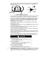
When levers are centered in the T-slot the drive system is in the neutral position.
With levers moved out in the T-slot the drive system is in the
neutral lock
position (See Fig. 6).
FIG. 6
MOTION CONTROL POSITIONS
By moving both levers an
equal
amount forward or back from the neutral position
the machine can be caused to move forward or backward in a straight line.
Movement of the
left lever forward
will cause the
left drive wheel
to rotate in a
forward direction. Movement of the
right lever forward
will cause the
right
drive wheel
to rotate in a forward direction. To
stop
forward travel, pull the
levers back to the neutral position.
To
turn left
while moving forward, move the
left lever
back toward neutral to
slow the left drive wheel.
To
turn right
while moving forward, move the
right lever
back toward neutral to
slow the right drive wheel.
To make a
zero turn
to the
left
, pull the left lever back beyond neutral while
holding the right lever slightly ahead of neutral.
To make a
zero turn
to the
right
, pull the right lever back beyond neutral while
holding the left lever slightly ahead of neutral.
Pulling the
levers back
from the neutral position will cause the respective drive
wheels to rotate in a
reverse
direction (spring tension can be felt when moving
into reverse from neutral).
To turn to the left while backing, move the left lever forward toward neutral. To
turn to the right while backing, move the right lever forward toward neutral.
CAUTION
POTENTIAL HAZARD
♦
Machine can spin very rapidly by positioning one lever
too much ahead of the other.
WHAT CAN HAPPEN
♦
Operator may lose control of the machine, which may
cause damage to the machine or injury.
HOW TO AVOID THE HAZARD
♦
Use caution when making turns.
♦
Slow the machine down before making sharp turns.
4.1.3
Blade Engagement Switch: Located just left of center on the console (left side of
ignition switch). Switch must be
pulled out
to the “
ROTATE
” position to engage
the blades. Switch is pushed in to the “
STOP
” position to stop the blades.
Summary of Contents for Laser Z LZ18KC523
Page 1: ......
Page 57: ... 52 8 ELECTRICAL DIAGRAM KOHLER 18 22 23 25 HP AIR COOLED UNITS Serial Nos 251 999 and Lower ...
Page 58: ... 53 ELECTRICAL DIAGRAM KOHLER 23 25 HP AIR COOLED UNITS Serial Nos 252 000 and Higher ...
Page 59: ... 54 ELECTRICAL DIAGRAM 22 23 HP KAWASAKI LIQUID COOLED UNITS ...
Page 60: ... 55 ELECTRICAL DIAGRAM KOHLER 26 HP EFI UNITS Serial Nos 251 999 and Lower ...
Page 61: ... 56 ELECTRICAL DIAGRAM KOHLER 26 HP EFI UNITS Serial Nos 252 000 and Higher ...
Page 62: ... 57 ELECTRICAL DIAGRAM 23 HP KAWASAKI AIR COOLED ...
Page 63: ... 58 ELECTRICAL DIAGRAM 27 HP KAWASAKI LIQUID COOLED ...
Page 64: ... 59 9 HYDRAULIC DIAGRAM ...
Page 67: ... 62 NOTES ...
Page 68: ... 63 SERVICE RECORD Date Description of Work Done Service Done By ...
Page 69: ... 64 ...


