background image

3UH

0

,QVWDOODWLRQ

#

3ODQQLQJ

##

506

953#

9HFWRU

#

'ULYH

#0#

+$

7968;7

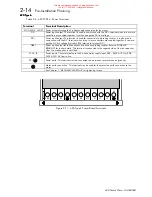
3 Phase
Rectifier

L1

L2

L3

Inverter
Circuits

DC-

DC+

Dynamic
Brake
Circuit

Input
3 Phase
Supply

DBR1

This connection is
made when the
braking option is not
fitted.

Brake
resistor

DC+

DC-

DC

Internal DC
Link choke

Motor
Drive
Outputs

Protective Earth

M1/U

M2/V

M3/W

)LJXUH

#516#0#

7\SH

#9#

6LPSOLILHG

#

%ORFN

#

'LDJUDP

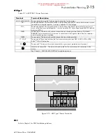
3 Phase
Rectifier

L1

L2

L3

Inverter
Circuits

DC-

DC+

Dynamic
Brake
Circuit

Input
3 Phase
Supply

DBR1

Brake
resistor

DC+

DC-

DC

Internal DC
Link choke

Motor
Drive
Outputs

DC

DBR2

Protective Earth

M1/U

M2/V

M3/W

)LJXUH

#517#0#

7\SH

#:#

6LPSOLILHG

#

%ORFN

#

'LDJUDP

This manual was downloaded on www.sdsdrives.com 

+44 (0)117 938 1800 - [email protected]

Summary of Contents for 620 Com

Page 1: ...ployed by a Eurotherm group company without written permission from Eurotherm Drives Ltd Although every effort has been taken to ensure the accuracy of this document it may be necessary without notice to make amendments or correct omissions Eurotherm Drives cannot accept responsibility for damage injury or expenses resulting therefrom RPSDWLEOH ZLWK 9HUVLRQ 71 6RIWZDUH This manual was downloaded o...

Page 2: ...rm Drives warrants the goods against defects in design materials and workmanship for the period of 12 months from the date of delivery on the terms detailed in Eurotherm Drives Standard Conditions of Sale IA058393C Eurotherm Drives reserves the right to change the content and product specification without notice This manual was downloaded on www sdsdrives com 44 0 117 938 1800 info sdsdrives com ...

Page 3: ...vironmental conditions of installation for safe and reliable operation Never perform high voltage resistance checks on the wiring without first disconnecting the product from the circuit being tested This equipment contains electrostatic discharge ESD sensitive parts Observe static control precautions when handling installing and servicing this product THESE WARNINGS AND INSTRUCTIONS ARE INCLUDED ...

Page 4: ...urn to factory for repair Use of unapproved parts may create a hazard and risk of injury WHEN REPLACING A PRODUCT IT IS ESSENTIAL THAT ALL USER DEFINED PARAMETERS THAT DEFINE THE PRODUCT S OPERATION ARE CORRECTLY INSTALLED BEFORE RETURNING TO USE FAILURE TO DO SO MAY CREATE A HAZARD AND RISK OF INJURY PACKAGING The packaging is combustible and if disposed of in this manner incorrectly may lead to ...

Page 5: ...running performance adjustment procedures Information is also provided on the function and set up of operational parameters using the Man Machine Interface MMI 37 5 8 0 81 7 21 2 6 This section provides reference information for the more advanced programming capabilities of the 620 Vector series controllers Each section describes a particular functional area and the associated menu options which a...

Page 6: ... RQW19 This manual was downloaded on www sdsdrives com 44 0 117 938 1800 info sdsdrives com ...

Page 7: ...111111 408 LJLWDO 2XWSXWV1111111111111111111111111111111111111111111111111111111111111111111111111111111 408 3LORW 2XWSXW111111111111111111111111111111111111111111111111111111111111111111111111111111111111 409 QFRGHU QSXWV 1111111111111111111111111111111111111111111111111111111111111111111111111111111 409 QFRGHU 6XSSO 2XWSXW1111111111111111111111111111111111111111111111111111111111111111111 409 6H...

Page 8: ...111111111111111111115048 0 11111111111111111111111111111111111111111111111111111111111111111111111111111111111111111111111111111115048 7 50 1 7 216 111111111111111111111111111111111111111111111111111111111111111111111111111111111111115049 KDSWHU 6 167 7 21 352 85 1752 8 7 21 11111111111111111111111111111111111111111111111111111111111111111111111111111111111111604 167 7 21 35 87 2161111111111111111...

Page 9: ...1111111111111111111111111111111 704 LVSOD DQG 0HQX 1111111111111111111111111111111111111111111111111111111111111111111111111111111 704 HILQLWLRQ RI WHUPV11111111111111111111111111111111111111111111111111111111111111111111111111 704 XQFWLRQ H V11111111111111111111111111111111111111111111111111111111111111111111111111111111111111 705 RPPDQG H V11111111111111111111111111111111111111111111111111111111...

Page 10: ...11111111111111111111111111111111111111111111111111111111111111111111118043 6WRS 5DWHV1111111111111111111111111111111111111111111111111111111111111111111111111111111111111111118043 ODUPV111111111111111111111111111111111111111111111111111111111111111111111111111111111111111111111118046 DOLEUDWLRQ111111111111111111111111111111111111111111111111111111111111111111111111111111111111111118047 7RUTXH RRS ...

Page 11: ...96 1 2 8 13876 111111111111111111111111111111111111111111111111111111111111111111111111111111 8096 1 2 8 2873876111111111111111111111111111111111111111111111111111111111111111111111111111 8097 1387611111111111111111111111111111111111111111111111111111111111111111111111111111111111111111111111111 8098 7 2873876111111111111111111111111111111111111111111111111111111111111111111111111111111111 8099 21...

Page 12: ...11111111111111111111111111111111111111111111111111111111111111111111111111111111111111111111111111111 06 5 7851 0 7 5 11111111111111111111111111111111111111111111111111111111111111111111111111111111 06 8527 50 5 9 6 203 1 6 111111111111111111111111111111111111111111111111111111111111 07 29 56 6 203 1 61111111111111111111111111111111111111111111111111111111111111111111111111111 07 KDSWHU 33 1 6 33 ...

Page 13: ...This manual was downloaded on www sdsdrives com 44 0 117 938 1800 info sdsdrives com ...

Page 14: ...1 5 6 5 37 21 The 620 Vector drive allows high performance speed control of AC asynchronous induction motors fitted with an encoder It is available with a range of power ratings in three variants 620STD STANDARD for use in systems incorporating analogue setpoints and logic control systems 620COM As above with the addition of a Serial port for use in Eurotherm Drives serial protocols and a referenc...

Page 15: ...ctory fitted option and usually fitted as standard 2 UL Type 1 Top Cover 3 Glandbox 20321 17 17 7 21 This manual refers to various connector terminals within the equipment which are accessible to the user for installation purposes An exploded view of a 620 Vector Drive is shown in Figure 1 1 00 3RZHU 7HUPLQDOV XWWRQV L LQJ 3RLQW L LQJ 3RLQW 6WDWXV V KDVVLV RU 6WDFN RQWURO RDUG 7HUPLQDOV L LQJ 3RLQ...

Page 16: ...ions Short circuit line line Short circuit line earth Earth fault Overcurrent 220 Overvoltage Undervoltage Stall Overspeed 5703 repeater error External trip Heatsink overtemperature Motor thermistor overtemperature LDJQRVWLFV DQG PRQLWRULQJ LDJQRVWLFV DQG PRQLWRULQJ LDJQRVWLFV DQG PRQLWRULQJ LDJQRVWLFV DQG PRQLWRULQJ Full diagnostics monitoring is provided by the MMI display and status LEDs QSXWV ...

Page 17: ...VH2 LUFXLW UHDNHU 43 48 53 734 734 964 4334 4584 4934 5334 SSUR 1 ORVV 3 3 433 463 543 5 3 693 843 9 3 63 3 4633 4933 6ZLWFKLQJ UHTXHQF 8N 6N RPPRQ GDWD 7 3 7 7 3 8 7 3 9 7 3 2XWSXW 9ROWDJH PD QSXW 9ROWDJH 2XWSXW 2YHUORDG 483 IRU 93V 2XWSXW UHTXHQF 3 WR 573 PELHQW 2SHUDWLQJ 7HPSHUDWXUH 5DQJH 3 WR 83ƒ 3 WR 73ƒ IRU 515N 6 3 0 7939 8 7 SH 4 3 WR 73ƒ DUWK HDNDJH XUUHQW 83P 1 3HUPDQHQW 3URWHFWLYH DUWKL...

Page 18: ...DPSOH 5DWH 6 QFKURQRXV ZLWK EORFN GLDJUDP 7HUPLQDO 7 LUHFW 23 414P61 41 9P6 IRU GULYH VL HV DQG XSZDUGV1 6 QFKURQRXV ZLWK EORFN GLDJUDP XUUHQW PD 1 4P 6P 7DEOH 407 QDORJXH QWHUIDFH 6SHFLILFDWLRQ LJLWDO QSXWV LJLWDO QSXWV LJLWDO QSXWV LJLWDO QSXWV QSXW YROWDJH 1RPLQDO 579 0D 1 639 QSXW LPSHGDQFH 7N Ω 6DPSOH 5DWH 6 QFKURQRXV ZLWK EORFN GLDJUDP 7KUHVKROG 9 ORZ 99 7 SLFDO 459 9LQ KLJK 4 9 7DEOH 408 LJ...

Page 19: ...M NoOfLines 60 7DEOH 40 RQWURO 7HUPLQDO 6SHFLILFDWLRQV QFRGHU 6XSSO 2XWSXW QFRGHU 6XSSO 2XWSXW QFRGHU 6XSSO 2XWSXW QFRGHU 6XSSO 2XWSXW 2XWSXW 9ROWDJH 43 0 549 3 WR 533P ORDG 499 49 5HFRPPHQGHG ORDG 1 7KH 2XWSXW 9ROWDJH PD EH VHW E DOWHULQJ WKH YDULDEOH 6HWXS 3DUDPHWHUV DOLEUDWLRQ QFRGHU 6XSSO µ1 5HFRPPHQGHG RDG XUUHQW 83 0 533P 6KRUW LUFXLW XUDWLRQ QGHILQLWH 7DEOH 40 QFRGHU 6XSSO 2XWSXW 6SHFLILFDW...

Page 20: ...RQQHFWRUV IRU 31 8PP 5 ZLUH1 7HUPLQDOV ZLOO DFFHSW XS WR 616PP 5 ZLUH 45 1 7LJKWHQLQJ WRUTXH 3189031 1P 80 OE0LQ 31750318 OE0IW 1 6SULQJ WHUPLQDO FRQQHFWRUV1 7HUPLQDOV ZLOO DFFHSW XS WR 31 PP 5 ZLUH 4 1 7DEOH 4044 953 W SH 7 PHFKDQLFDO GHWDLOV 953 7 3 8 953 7 3 8 953 7 3 8 953 7 3 8 0 16 216 5HIHU WR ILJXUH 614 02817 1 25 17 7 21 9HUWLFDO 7 45NJ 5 2 5 1 5HIHU WR ILJXUH 614 32 5 7 50 1 7 216 08 VOR...

Page 21: ...H 4 5 WHUPLQDOV RPSDFW KLJK FXUUHQW WHUPLQDO EORFNV1 7HUPLQDOV DFFRPPRGDWH ZLUH UDQJH 6619043 15PP 5 50723 7LJKWHQLQJ WRUTXH 531P 4 8OE0LQ 4719OE0IW 1 E 1 1 LQWHUFRQQHFWLRQ WHUPLQDOV 0 RPSDFW KLJK FXUUHQW WHUPLQDO EORFNV1 7HUPLQDOV DFFRPPRGDWH ZLUH UDQJH 66190485PP 5 5 0633NFPLO 0 0 7LJKWHQLQJ WRUTXH 63181P 5 3OE0LQ 5518OE0IW F DUWK JURXQG RPSDFW KLJK FXUUHQW WHUPLQDO EORFNV1 7HUPLQDOV DFFRPPRGDWH...

Page 22: ...46 333 5 V XVH 5DWLQJ2 LUFXLW UHDNHU 7 533 583 633 683 733 783 883 933 SSUR 1 ORVV 6N N 517 51 618 716 71 817 91 18 6ZLWFKLQJ UHTXHQF 6N 2XWSXW 9ROWDJH PD QSXW 9ROWDJH 2XWSXW 2YHUORDG 483 IRU 93 VHFRQGV 2XWSXW UHTXHQF 3 WR 453 DQ QOHW WHPSHUDWXUH 5DQJH 3 WR 73 3 5DWLQJ 353 QFORVXUH 333 SRZHU WHUPLQDOV DUWK HDNDJH XUUHQW 433P 1 3URGXFW PXVW EH SHUPDQHQWO HDUWKHG 7DEOH 4048 1 Suitable for earth refe...

Page 23: ...t Rating Bussmann Model No 40A 50A 63A 100A 125A 170M3808 170M3809 170M3810 170M3812 170M3813 7DEOH 4049 0 XVVPDQQ QWHUQDWLRQDO XVHV 5DWHG 9939DF Model 620 Type 7 Series These devices are provided with solid state short circuit output protection Branch circuit protection should be provided as specified in the National Electrical Code NEC NFPA 70 Short Circuit Ratings Model 620 Type 4 5 6 Series Su...

Page 24: ...3 GLUHFW FRQGXLW FRQQHFWLRQ DQG 8 7 SH 4 RSWLRQV OLPDWLF RQGLWLRQV ODVV 6N6 DV GHILQHG E 1834 4 3ROOXWLRQ HJUHH 5 QVWDOODWLRQ 2 2YHUYROWDJH DWHJRU 6 7DEOH 404 953 6HULHV HQYLURQPHQWDO UHTXLUHPHQWV 3URGXFW RGH All 620 units are fully identified using an eleven block alphanumeric code as shown in figure 1 2 This code details the drive calibration and settings on despatch from the factory The product...

Page 25: ...HUV VSHFLI LQJ DQ IHHGEDFN RSWLRQ LQVWDOOHG RYHU DQG DERYH WKH VWDQGDUG IHDWXUHV RI WKH SURGXFW H1J1 QFRGHU LUH0HQGHG 3333 12 RXU FKDUDFWHUV VSHFLI LQJ WKH FRPPXQLFDWLRQV SURWRFRO DQG LWV KDUGZDUH LPSOHPHQWDWLRQ PHWKRG 1R FRPPXQLFDWLRQV RSWLRQV ILWWHG QGLFDWHV WKH SDUWLFXODU FRPPXQLFDWLRQV RSWLRQ 333 12 7KUHH FKDUDFWHUV VSHFLI LQJ DQ RSWLRQDO ORDGHG VRIWZDUH 1R VRIWZDUH RSWLRQV ORDGHG QGLFDWHV WKH...

Page 26: ...ting 380 460v input supply Eurotherm Drives livery Enclosed mechanical package IP20 No additional optional operator station UK language Wire ended 15V encoder option No optional communications No optional loaded software Brake switch fitted with default value resistors supplied No aux supply option fitted No special options This manual was downloaded on www sdsdrives com 44 0 117 938 1800 info sds...

Page 27: ...4047 3URGXFW 2YHUYLHZ 953 9HFWRU ULYH 0 7968 7 This manual was downloaded on www sdsdrives com 44 0 117 938 1800 info sdsdrives com ...

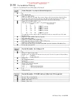
Page 28: ...quency for a particular motor speed Analogue inputs to the microprocessor are digitised and can be used to set parameters such as speed Digital inputs to the microprocessor signal various commands and conditions such as stop start and required direction of rotation Digital outputs from the microprocessor e g Health can be used by external control equipment A detailed block diagram of the logical b...

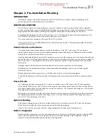
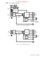
Page 29: ...ing option is not fitted Brake resistor DC DC DC Internal DC Link choke Motor Drive Outputs Protective Earth M2 V M3 W LJXUH 514 0 7 SH 7 6LPSOLILHG ORFN LDJUDP 3 Phase Rectifier L1 L2 L3 Inverter Circuits DC DC Dynamic Brake Circuit Input 3 Phase Supply DBR1 Brake resistor DC DC DC Internal DC Link choke Motor Drive Outputs DC Protective Earth M1 U M2 V M3 W LJXUH 515 0 7 SH 8 6LPSOLILHG ORFN LDJ...

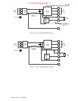
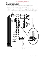
Page 30: ...ernal DC Link choke Motor Drive Outputs Protective Earth M1 U M2 V M3 W LJXUH 516 0 7 SH 9 6LPSOLILHG ORFN LDJUDP 3 Phase Rectifier L1 L2 L3 Inverter Circuits DC DC Dynamic Brake Circuit Input 3 Phase Supply DBR1 Brake resistor DC DC DC Internal DC Link choke Motor Drive Outputs DC DBR2 Protective Earth M1 U M2 V M3 W LJXUH 517 0 7 SH 6LPSOLILHG ORFN LDJUDP This manual was downloaded on www sdsdri...

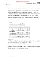
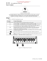
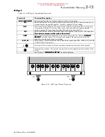
Page 31: ...minals The MCB details are listed in Table 2 1 and the power terminals are shown in Figures 2 9 to 2 12 L3 L1 MCB1 MOTOR M L1 L2 FILTER OPTIONAL M2 V M1 U M3 W LABELLED DB1 DB2 ON TYPE 7 CHASSIS RAM P SPEED L3 PE L2 F STOP GND C2 C1 B4 B5 E STOP C6 C3 B7 STOP COAST STOP FAST START A A ENCODER MOTOR THERMISTOR B 15V 0V B E 620 VECTOR DRIVE B8 B9 24V 24V A1 A2 ASSY A4 A3 A7 A8 DBR B1 A9 E E B2 DC DC...

Page 32: ...4VDC CON1 PILOT RELAY OPTIONAL PE L2 L3 B5 B6 C1 F3 F4 F2 M C B 2 F STOP B7 B8 C2 C5 F5 E STOP FAST STOP J O G START ENABLE A A SPEED HEALTHY DIG O P1 ZERO DIG O P2 DRIVE RL S RL S READY DIG O P3 DRIVE RL S E N C O D E R B B 15V 0V M O T O R E B9 E2 620 VECTOR DRIVE E1 E6 E7 E3 E4 E8 A1 A2 H O L D R A M P 1 2 PRESET INPUTS BRAKE RESISTOR E9 E5 D B R A4 A3 A7 A8 DC DC E B1 A9 B2 E ASSY DYNAMIC BRAK...

Page 33: ... load current of the motor 7DEOH 504 0 UHTXLUHPHQWV 7 SH 7 SH 7 SH 7 SH 3RZHU N 3RZHU N 3RZHU N 3RZHU N 53 0573Y 53 0573Y 53 0573Y 53 0573Y 6 30793Y 6 30793Y 6 30793Y 6 30793Y 31 8 43 43 414 43 12 418 43 53 7 515 53 43 713 53 53 818 12 53 18 12 53 818 63 12 18 73 12 8 4413 12 65 4813 12 73 4413 96 12 4813 433 12 4 13 12 83 9 4 18 433 12 5513 12 96 6313 12 433 6 13 12 433 5513 458 12 6313 493 12 6 ...

Page 34: ...8 6HULDO 3RUW 5 5 5 5 12 12 12 12 7UDQVPLW 6 6 6 6 12 12 12 12 7UDQVPLW 0 2 5HFHLYH 0 7 7 7 7 12 12 12 12 7UDQVPLW 2 5HFHLYH LQN LEUH 2SWLFV1 5HG 5HG 5HG 5HG 12 12 12 12 7UDQVPLW 3ULPDU 953 RQO ODFN ODFN ODFN ODFN 12 12 12 12 5HFHLYH 3ULPDU HHGEDFN QFRGHU 5HIHUHQFH QFRGHU 953 RP 953 RQO 4 4 4 4 4 4 4 4 2 5 5 5 5 5 5 5 5 2 6 6 6 6 6 6 6 6 2 7 7 7 7 7 7 7 7 2 8 8 8 8 8 8 8 8 2 9 9 9 9 9 9 9 9 2 3RZH...

Page 35: ...KLQH1 7KHUPLVWRUV KDYH D ORZ UHVLVWDQFH W SLFDOO 533Ω XS WR D UHIHUHQFH WHPSHUDWXUH 458 1 ERYH WKLV WHPSHUDWXUH WKHLU UHVLVWDQFH ULVHV UDSLGO WR JUHDWHU WKDQ 5333Ω1 0RWRU RYHU WHPSHUDWXUH VHQVRUV VKRXOG EH FRQQHFWHG LQ VHULHV EHWZHHQ WHUPLQDOV 4 DQG 51 PRWRU RYHU WHPSHUDWXUH DODUP ZLOO EH LQGLFDWHG LI WKH H WHUQDO UHVLVWDQFH EHWZHHQ 4 DQG 5 H FHHGV 519NΩ 533Ω1 7KH DODUP LV UHVHW DW 414NΩ 533Ω1 7HU...

Page 36: ... 4 4 4 1 QDORJXH VFUHHQ FRQQHFWLRQ1 5 5 5 5 6LJQDO 3Y 6 6 6 6 5DPS 23 4 EL0GLUHFWLRQDO LQSXW WKDW LV VXPPHG ZLWK 5 WR IRUP WKH LQSXW WR WKH 6 VWHP 5DPS1 43Y XOO VSHHG 0 43Y 5HYHUVH IXOO VSHHG 7 7 7 7 LUHFW 23 5 7ULP LQSXW GLUHFW LQWR VSHHG ORRS ZLWK KLJK VSHHG FRXSOLQJ1 8VHG IRU H WHUQDO ORRSV L1H1 SRVLWLRQ FRQWUROOHUV1 43Y 433 6SHHG WULP 0 43Y 0433 6SHHG WULP 8 8 8 8 QDORJ 223 4 6SHHG IHHG0EDFN 9...

Page 37: ... LQSXWV1 9 9 9 9 LJLWDO 223 4 52 63 HIDXOW FRQILJXUDWLRQ1 FWLYH LJK DW HUR VSHHG1 1 LJLWDO 223 5 HDOWK HIDXOW FRQILJXUDWLRQ1 FWLYH LJK ZKLOH WKH GULYH LV HDOWK RU 67 57 2 2 DUH ORZ1 LJLWDO 223 6 5HDG HIDXOW FRQILJXUDWLRQ1 FWLYH LJK RQFH WKH GULYH KDV VXFFHVVIXOO FRPSOHWHG LV SUH0VWDUW FKHFNV DQG LI QDEOHG ZLOO UXQ1 57Y SRZHU DV WHUPLQDO 7HUPLQDO 1XPEHU 7HUPLQDO HVFULSWLRQ 0 X 1 QDORJXH 22 4 4 4 4 ...

Page 38: ...ght meter can be used to check that the received power at the far end of the optical fibre is within limits The switch must be OFF in the normal operation 7DEOH 516 7UDQVPLWWHU 3RZHU 3 6ZLWFKHV 527 ZLUH 6ZLWFK 4 70 LUH 5607 8 2II 50 LUH 5607 8 1RW 6XSSRUWHG 2Q 7 3RZHU 6ZLWFK 6 6ZLWFK 7 6ZLWFK 8 RZ 2II GRQ W FDUH 2II 0HGLXP 2Q 2II 2II LJK 2Q 2Q 2II 7HVW 0RGH GRQ W FDUH GRQ W FDUH 2Q HHGEDFN QFRGHU ...

Page 39: ...Q WR D EUDNLQJ UHVLVWRU1 W LV DOVR XVHG LQ FRQMXQFWLRQ ZLWK WKH 0 WHUPLQDO ZKHQ WZR RU PRUH FRQWUROOHUV DUH FRXSOHG WRJHWKHU1 W FDUULHV D SRVLWLYH OLQN YROWDJH W SLFDOO 9339 UHIHUUHG WR WHUPLQDO 0 1 54 3RZHU LQSXW2RXWSXW IRU WKH FRQQHFWLRQ RI D G QDPLF EUDNLQJ UHVLVWRU1 5HIHU WR 1 0 5 1 IRU IXUWKHU GHWDLOV1 7KLV WHUPLQDO LV FRQQHFWHG WR WKH QHJDWLYH VLGH RI WKH OLQN FDSDFLWRU ZKHQ WKH EUDNH RSWLRQ...

Page 40: ...XVWRPHU FRQQHFWLRQ PXVW EH PDGH WR WKLV WHUPLQDO1 1R FXVWRPHU FRQQHFWLRQ PXVW EH PDGH WR WKLV WHUPLQDO1 1R FXVWRPHU FRQQHFWLRQ PXVW EH PDGH WR WKLV WHUPLQDO1 1R FXVWRPHU FRQQHFWLRQ PXVW EH PDGH WR WKLV WHUPLQDO1 54 54 54 54 3RZHU LQSXW2RXWSXW IRU WKH FRQQHFWLRQ RI D G QDPLF EUDNLQJ UHVLVWRU1 5HIHU WR 1 0 1 0 1 0 1 0 5 1 5 1 5 1 5 1 IRU IXUWKHU GHWDLOV1 7KLV WHUPLQDO LV FRQQHFWHG WR WKH QHJDWLYH VL...

Page 41: ... FDUULHV D SRVLWLYH OLQN YROWDJH W SLFDOO 9339 UHIHUUHG WR WHUPLQDO 0 1 54 3RZHU LQSXW2RXWSXW IRU WKH FRQQHFWLRQ RI D G QDPLF EUDNLQJ UHVLVWRU1 5HIHU WR 1 0 5 1 IRU IXUWKHU GHWDLOV1 7KLV WHUPLQDO LV FRQQHFWHG WR WKH QHJDWLYH VLGH RI WKH OLQN FDSDFLWRU ZKHQ WKH EUDNH RSWLRQ LV QRW ILWWHG1 4 5 6 3RZHU LQSXWV1 7KHVH WHUPLQDOV DUH WKH 60SKDVH PDLQV VXSSO LQSXW 6 3 0 7939 43 RU 53 0 5739 43 OLQH0WR0OLQ...

Page 42: ...IRU FRQQHFWLRQ WR D EUDNLQJ UHVLVWRU1 5HIHU WR 1 0 5 1 IRU IXUWKHU GHWDLOV1 7KLV WHUPLQDO LV FRQQHFWHG WR WKH QHJDWLYH VLGH RI WKH OLQN FDSDFLWRU ZKHQ WKH EUDNH RSWLRQ LV QRW ILWWHG1 55 3RZHU RXWSXW1 7KLV WHUPLQDO LV XVHG IRU FRQQHFWLRQ WR D EUDNLQJ UHVLVWRU1 4 5 6 3RZHU LQSXWV1 7KHVH WHUPLQDOV DUH WKH 60SKDVH PDLQV VXSSO LQSXW 6 3 0 7939 43 RU 53 0 5739 43 OLQH0WR0OLQH1 3 2 3RZHU HDUWK1 7KLV WHUP...

Page 43: ...orrect tooling as described in the Installation Instructions provided with each Lug Kit The following terminal kit is available for the connection of Power Cabling 3URGXFW 6XSSO 9ROWDJH RQVWDQW 7RUTXH 4XDGUDWLF 7RUTXH LW 1R1 XJ 6L H PS 3DUW 1R1 953 6 3 0 7939 44N 000 6 8 8 8559604 6 3 0 7939 48N 000 53 0 5739 818N 000 53 0 5739 18N 000 This manual was downloaded on www sdsdrives com 44 0 117 938 1...

Page 44: ...URRENT CONTROLLER START JOG AUX START AUX JOG AUX DISABLE EXTERNAL TRIP OTHER ALARMS STALL SPEED FDBK DELAY TORQUE SPEED FDBK 126 STOP 0 SPEED SIGN 1 RATIO 1 SIGN 0 RATIO 0 372 INPUT 1 INPUT 0 INPUT 2 385 370 LIMIT 195 LIMIT 386 RATIO 1 SIGN 1 RATIO 0 384 383 INPUT 1 376 INPUT 0 INPUT 2 382 375 SETPOINT SUM 3 381 SIGN 0 378 377 LIMIT aX b aX b aX b aX b aX b aX b DIRECT I P MAX DIRECT I P MIN DIRE...

Page 45: ...3UH0 QVWDOODWLRQ 3ODQQLQJ 504 953 9HFWRU ULYH 0 7968 7 This manual was downloaded on www sdsdrives com 44 0 117 938 1800 info sdsdrives com ...

Page 46: ... Mounting dimensions and suitable fixing bolts are shown in Figure 3 1 The 620 Vector Drive must be mounted vertically on a cool solid flat vertical surface It must be fixed using 4 bolts or screws of the correct size through the fixing points provided at each corner at the rear of the unit The fixing points are in the form of keyholes and slots to simplify fastening or removal 9HQWLODWLRQ In norm...

Page 47: ...LW KROH VL H PP 1 4 5 7 SH 7 64 55 48 633 533 47 09 3 43 6 8 73 463 65 53065 7 SH 8 79 55 48 783 533 47 09 3 43 868 73 463 65 53065 7 SH 9 9 5 567 5 983 533 4 44 0 433 73 8 73 463 53073 65073 7 SH 6 6 669 33 6 3 47 4 043 583 83 4458 453 633 0 770 9 Table 3 1 620 Mounting Arrangements Full details of through panel mounting of type 7 not available at time of going to press Please contact Eurotherm D...

Page 48: ...rations apply to all installations 1 Power cables must be rated at a minimum of 110 of the expected supply current 2 Power cables particularly 3 phase motor cables must be routed well away from cables carrying setpoints or feedback signals screened motor feedback cables and cables from other electronic equipment in the same plant 3 The motor supply cables should be screened to avoid causing undue ...

Page 49: ...818 9 48 18 73 18 43 4 0 83 4518 49 55 44 96 4 49 63 48 433 6 68 6 4 433 6 68 78 55 458 83 83 88 63 493 98 3 8 6 533 8 8 Cable diameters listed assume the conductors are in free air Fuses are standard type with slow blow characteristic or a circuit breaker NOTE These are typical values only If in doubt please observe your national standards or local electricity supply regulations For installations...

Page 50: ...6 02 953 7 3 7 1 7 3 8 6 5 6 02 953 7 3 7 1 7 3 8 6 5 6 XELFOH00RXQWHG 353 0RGHOV XELFOH00RXQWHG 353 0RGHOV XELFOH00RXQWHG 353 0RGHOV XELFOH00RXQWHG 353 0RGHOV 0RGHO 953 7 SH 7 6HULHV 0RGHO 953 7 SH 7 6HULHV 0RGHO 953 7 SH 7 6HULHV 0RGHO 953 7 SH 7 6HULHV Protective earthing arrangements for these models are provided by a single size M4 diameter earth terminal located at the centre of the power te...

Page 51: ...d are intended to be used with protective conductors terminated with compression terminations sized to accept the M5 diameter bolt fitted and the conductor size selected The single incoming protective conductor shall be of 10mm2 cross sections minimum permanent earthing in Europe and be connected to the terminal marked PE as shown in the drawing below whilst the motor protective conductor shall be...

Page 52: ...th terminals are identified with the symbol IEC 417 Symbol 5019 and are intended to be used with protective conductors terminated with compression terminations sized to accept the M5 diameter bolt fitted and the conductor size selected The single incoming protective conductor shall be of 10mm2 cross section minimum for permanent earthing in Europe connected to the terminal marked PE as shown in th...

Page 53: ...ed to the terminal marked PE as shown in the drawing below whilst an adequately rated motor protective conductor shall be connected to the remaining earth terminal block The incoming protective earth conductor will be 10mm2 in cross section so the drives will be permanently earthed for Europe MOTOR PROTECTIVE TERMINAL GRD GLAND BOX SUPPLY PE GRD CUBICLE AND WALL MOUNTING PE GRD CONNECTIONS 620 TYP...

Page 54: ...ws back from the motor into the DC link capacitors within the drive This causes the DC link voltage to rise If the DC link voltage exceeds 810V for the 400V build or 420V for the 230V build then the drive will trip to protect the capacitors and the inverter power devices The amount of energy that can be absorbed in the capacitors is relatively small typically more than 20 braking torque will cause...

Page 55: ...eed rpm tb braking time s tc cycle time s Information on the peak power rating and the average power rating of the resistors must be obtained from the resistor manufacturer Alternatively if this information is not available then a large safety margin must be incorporated to ensure that the resistors are not overloaded Eurotherm Drives can supply suitable brake resistor assemblies as detailed over ...

Page 56: ...G UDWLQJ 5833 5833 LPHQVLRQV 4 PP 498 668 5 PP 479 649 6 PP 458 5 8 PP 63 63 PP 93 93 PP 816 816 D PP 46 46 E PP 4 4 O LQJ OHDG OHQJWK PP 833 833 OHFWULFDO RQQHFWLRQ 08 VSDGH 08 ULQJ Resistor Derating Graph Ambient Temp C of Rated Power 0 20 40 60 80 100 0 25 50 75 100 125 150 175 200 chassis mounted free air These resistor should be mounted on a heatsink back panel and covered to prevent injury f...

Page 57: ...93 9ROWV 58Ω 0LQ UHVLVWRU YDOXH 53 0 573 9ROWV 4518Ω KDVVLV W SH 9 KDVVLV W SH 9 KDVVLV W SH 9 KDVVLV W SH 9 7 SLFDO PRWRU UDWLQJ 6 3 0 793 9ROWV 4 N 55N 63N 6 N 7 SLFDO PRWRU UDWLQJ 53 0 573 9ROWV 0 44N 48 Z 4 N XUUHQW UDWLQJ 53V PD 78 78 98 8 0D GXW F FOH 63 63 63 63 0LQ UHVLVWRU YDOXH 6 3 0 793 9ROWV 4 Ω 4 Ω 4418Ω 43Ω 0LQ UHVLVWRU YDOXH 53 0 573 9ROWV 0 18Ω 9Ω 8Ω KDVVLV W SH KDVVLV W SH KDVVLV ...

Page 58: ... peak and average power dissipation resistance and voltage rating This section describes how to select the right resistor for the application When the motor is decelerating a load the amount of power it creates is determined by the inertia of the load and the time the change in speed takes The rate of change is determined by the MMI parameter RAMP DOWN TIME DOFXODWLQJ 3RZHU LVVLSDWLRQ DOFXODWLQJ 3...

Page 59: ... resistor capable of dissipating 1100W peak for 10 seconds and an average power of 100W will be required Information on the peak power rating and the average power rating of resistors must be obtained from the resistor manufacturer Alternatively if this information is not available then a large safety margin must be incorporated to ensure that the resistors are not overloaded The resistance of the...

Page 60: ...istor For example four Eurotherm CZ057146 56 Ω 220W continuous resistors in series Total resistance 56 Ω 56 Ω 56 Ω 56 Ω 224 Ω Four Eurotherm CZ057146 56 Ω 220W continuous resistors in parallel Total resistance 56 Ω 14 Ω 4 Continuous power ratings in both cases are 880W four times 220W Peak powers are similarly multiplied by four Series and parallel networks can be combined as shown in Figure 3 5 T...

Page 61: ...th the recommended EMC filters in accordance with the following instructions The subject of EMC is explored in more detail in a separate Eurotherm Application Manual entitled EMC Installation Guidelines for modules and systems part number HA388879 available from your local Eurotherm office 0 LOWHUV WR 5HGXFH LQH RQGXFWHG 1RLVH An EMC supply filter may be used with each 620 drive module to reduce t...

Page 62: ... QVWDOODWLRQ 3URFHGXUH 604 953 9HFWRU ULYH 0 7968 7 LJXUH 60 1 LOWHU XELFOH 0RXQWLQJ HWDLOV 953 W SHV 7 8 This manual was downloaded on www sdsdrives com 44 0 117 938 1800 info sdsdrives com ...

Page 63: ...HWDLOV 953 W SHV 7 8 1 127 RX PXVW ILW WKH 953 PRGXOH ZLWK WKH WRS FRYHU JODQG ER DQG WUXQNLQJ DV VXSSOLHG1 OO LQWHUFRQQHFWLQJ OHDGV EHWZHHQ WKH 953 DQG WKH ILOWHU PXVW EH HQFORVHG ZLWKLQ WKH GXFW1 This manual was downloaded on www sdsdrives com 44 0 117 938 1800 info sdsdrives com ...

Page 64: ... QVWDOODWLRQ 3URFHGXUH 604 953 9HFWRU ULYH 0 7968 7 LJXUH 60 1 LOWHU 0RXQWLQJ HWDLOV 953 7 SH 9 1 This manual was downloaded on www sdsdrives com 44 0 117 938 1800 info sdsdrives com ...

Page 65: ...6053 QVWDOODWLRQ 3URFHGXUH 953 9HFWRU ULYH 0 7968 7 LJXUH 60431 LOWHU 0RXQWLQJ HWDLOV 953 7 SH 1 This manual was downloaded on www sdsdrives com 44 0 117 938 1800 info sdsdrives com ...

Page 66: ...ly connected to the filter and drive module gland box NOTE Metal surfaces such as eloxized or yellow chromed e g with cable mounting or 35 mm DIN rails screws and bolts have a high RF impedance which can be very detrimental for EMC performance Care should be taken to ensure that the protective earth PE conductor exiting from the filter is connected to the protective earth connection of the 620 dri...

Page 67: ...are not suitable for personnel protection Another means of providing personal safety must be provided for see EN50178 VDE0160 0LQLPLVLQJ 5DGLDWHG PLVVLRQV All 620 drive modules can be made to comply with the most stringent radiated emission limits of EN55011 1991 Class B by simply mounting inside an enclosure with 10 dB attenuation between 30 and 100 MHz which would typically be the attenuation pr...

Page 68: ...panel Beware of constructions using insulating mounting panels or undefined mounting structures A single point earthing strategy should be followed for a single drive module mounted in an enclosure as shown in figure 3 11 The protective earth connection PE to the motor must run inside the screened cable between the motor and 620 drive module where it is to be connected to the motor protective eart...

Page 69: ... of cable entry as possible For optimum EMC performance copper rails with a substantial cross section should be used for the busbar Screened cables are best u clamped to the busbars to ensure an optimum HF connection The five separate earth busbars should be insulated from the mounting panel and connected to a single earth point star point near the PE or PEN terminal of the main supply Flexible la...

Page 70: ...r EMC purposes use screened cable Always terminate the screen at the drive Normally the screen is terminated within the encoder housing follow the encoder manufacturers instructions Motor Cable length Limitations Screened armoured cable has significant capacitance between the conductors and the screen which increases linearly with cable length Typically this is 200 pF per metre but this will vary ...

Page 71: ...sy and sensitive cables is a problem This can be minimised by separating parallel runs by at least 0 25m and minimising the length of parallel runs For long parallel runs 10 m the separation should be increased proportionally For example if the parallel runs were 50 m then the separation would be 50 10 0 25 m 1 25 m In addition the coupling between two cables which must cross is minimised if they ...

Page 72: ... system LVSOD DQG 0HQX The MMI display comprises two lines of plain text information to provide access to the various menu options and parameters The top line contains the title of the current menu or parameter and the second contains either one of the options within the menu or the value or status of the parameter 127 127 127 127 There are two user views of the MMI REDUCED and FULL The reduced vi...

Page 73: ...nd and describes its function M MENU The MENU select key allows the user to access the menu level or function indicated on the bottom line of the display This key does not alter any of the stored drive parameters Pressing this key while in LOCAL MODE LOCAL LED illuminated shows the actual speed of the motor as a percentage of the maximum speed If FULL MENUS are enabled then pressing the M key whil...

Page 74: ...UP and DOWN can be used to control the motor speed and direction Press the LOCAL button to return to REMOTE MODE the MMI will return to the last accessed place in the main menu PROG PROG When in LOCAL MODE pressing the PROG button switches back to the main MMI menu At the point it was last accessed from REMOTE MODE while still remaining in LOCAL MODE This enables changes to be made to parameters n...

Page 75: ...threshold The LED flashes slowly during Autotune described later BRAKE If this LED is on it indicates that the DC link voltage inside the drive has risen above the dynamic braking threshold Chapter 3 DYNAMIC BRAKING describes this in more detail LOCAL This LED indicates the drive is in LOCAL MODE when illuminated 1 9 7 1 7 00 0 18 6758 785 The MMI comprises several hundred menu options shown in Fi...

Page 76: ...M E M E M E M E MENU A OPTION PARAM A PARAM A VALUE PARAM B VALUE PARAM B VALUE MENU D PARAM A PARAM C VALUE OPTION PARAM B PARAM B PARAM C VALUE 1 VALUE 2 etc etc 867 3 5 0 7 56 etc etc 5 21 3 5 0 7 56 H1J1 1267 6 LJXUH 715 0 8VLQJ WKH 00 This manual was downloaded on www sdsdrives com 44 0 117 938 1800 info sdsdrives com ...

Page 77: ...s parameters Refer to Chapter 5 for further details 6HW0XS 3DUDPHWHUV 6HW0XS 3DUDPHWHUV 6HW0XS 3DUDPHWHUV 6HW0XS 3DUDPHWHUV The SETUP PARAMETERS option provides the user with the facility to adjust and set a large number of drive parameters Refer to SETUP PARAMETERS in this chapter for further details 3DVVZRUG 3DVVZRUG 3DVVZRUG 3DVVZRUG The PASSWORD option allows the user to protect the setup para...

Page 78: ... cooling fan is intact and free of obstructions 6HWXS 6WHS 5 QVXUH 7KH 6DIHW 2I 7KH RPSOHWH 6 VWHP Next ensure the safety of the complete system when the drive is energised In particular ensure 1 That no personnel are at risk of injury or inconvenience when the drive system is energised 2 That rotation of the motor in either direction will not cause damage 3 That other equipment will not be advers...

Page 79: ...his speed will be the 100 speed referred to elsewhere in the MMI Use the and buttons to set the MAX SPEED RPM parameter to the required figure Press E It is important at this stage to set MAX SPEED RPM to the highest value that you are likely to be using This is because the autotune will only set up the magnetising current values up to this speed If at a later stage you wish to run the motor faste...

Page 80: ...AT THE EMERGENCY STOP CIRCUITS FUNCTION CORRECTLY BEFORE RUNNING THE MOTOR FOR THE FIRST TIME WHEN THE DRIVE IS RUN FOR THE FIRST TIME ROTATION WILL BE OF UNKNOWN DIRECTION MAY BE JERKY AND SPEED CONTROL MAY NOT OPERATE CORRECTLY ENSURE THAT NO MACHINERY CONNECTED TO THE MOTOR WILL BE DAMAGED BY UNPREDICTABLE MOTION 1 Press LOCAL to put the drive into LOCAL MODE The LOCAL LED should light 2 Use th...

Page 81: ...eds up to the value set in MAX SPEED RPM At each speed it will set up the magnetising current for this motor When it has finished it will then calculate the rotor time constant If any error messages occur on the MMI refer to Chapter 6 Alarms If the autotune fails to run but no error message appears on the MMI this may be due to a wrong configuration in the autotune menu This menu contains 2 flags ...

Page 82: ...380 460v At this stage the 620 Vector drive thinks that it is a 75kW model It is vitally important that it is configured for the correct power rating or irreparable damage may occur to the drive when it attempts to run the motor Press the and buttons to step through the range of power ratings until the displayed value is the same as the rating on the identification label on the side of the drive P...

Page 83: ...7045 6HWWLQJ0XS DQG RPPLVVLRQLQJ 953 9HFWRU ULYH 0 7968 7 This manual was downloaded on www sdsdrives com 44 0 117 938 1800 info sdsdrives com ...

Page 84: ...RAMP QUENCH 56 FALSE RAMP HOLD 57 TRUE Linked to 281 h SPECIAL 777 FALSE 7DJ LV FRQQHFWHG WR WDJ 5 4 Figure 5 1 Set up Parameter entry These tag numbers may be used to reconfigure the block diagram if the default configuration shown in figure 2 17 does not provide the functionality required Reconfiguring is done using source tags destination tags internal links Analogue and digital inputs have des...

Page 85: ...ue 3 Find Digital Inputs menu and select DIGIN 1 E2 4 Go into this menu and find Destination Tag Set this to the External Reset tag number 62 which may be found in section System Ramp or in the tag number list in the appendix chapter 9 5 Return to Configure Enable flag and set this to false 03 5 Bring Current Feedback to analogue output 2 torque demand is normally connected to this output by defau...

Page 86: ...from 0 to 100 DPSOH A change of Ramp Input from 10 to 50 with an acceleration time of 60 Seconds will take 50 10 100 60 Secs IIHFW RI 6 RQ 5DPS WLPHV1 1 x 100 3 5 x SRamp Time Ramp Time Ramp Actual Zero ramp times are a special case where the ramp can be effectively by passed RAMP QUENCH While TRUE the ramp input is held at zero NOTE This parameter is automaticall set TRUE during a normal stop if ...

Page 87: ...mp is held in reset EXTERNAL RESET does not depend on AUTO RESET for its operation Ramp Reset Definition Ramp Reset System Reset AND Auto Reset OR External Reset NOTE Reset overrides ramp hold RESET VALUE This value is pre loaded directly into the output while Ramp Reset is TRUE or at power up In order to catch a spinning load smoothly bumpless transfer or Fly Catching connect speed feedback TAG 7...

Page 88: ... SET UP SETPOINT Actual value of local setpoint LOCAL KEY ENABLE Enables the local key on the op station this must be set TRUE to allow the operator to toggle between local and remote modes START UP VALUES SETPOINT Default Value of local setpoint on power up REV DIRECTION Default Value of local direction on power up PROGRAM Default mode of op station prog key on power up LOCAL Default mode of op s...

Page 89: ...nnections Start Aux Jog Jog Aux Enable Enable Aux Start Drive Enable Drive Start Drive Jog 9 Figure 5 5 Aux I O Start Jog and Enable Also allow the drive to be started and stopped by software alone These parameters are by default connected to there respective terminals 51 1 CARE MUST BE TAKEN IN RECONFIGURING THE START JOG AND ENABLE INPUTS AS THESE TAGS MAY DIRECTLY ENABLE THE DRIVE IF THERE ARE ...

Page 90: ...rved 13 0x2000 Reserved 14 0x4000 Reserved 15 0x8000 Reserved 6 4 67 786 7 5 21 Reserved bits are undefined when read Bit Number Mask Name Comment 0 lsb 0x0001 Coast Stop Coast Stop demanded 1 0x0002 Program Stop Program Fast Stop demanded 2 0x0004 Disable Enable demanded 3 0x0008 Run Drive Start demanded 4 0x0010 Jog Drive Jog demanded 5 0x0020 Reserved Undefined 6 0x0040 Alarm Unacknowledged ala...

Page 91: ...s must be TRUE ACK ALARM 166 AND REMOTE SEQ 786 BIT 8 NOTE if remote sequencing is not enable then REMOTE SEQ 786 BIT 8 is forced TRUE 5 027 75 3 50 The Remote trip alarm is designed to signal a network fault to the drive When using the 6204 Profibus interface all outputs are set to zero on link fail If one of the outputs is REMOTE SEQ 786 the drive will trip after a delay specified by Remote Dela...

Page 92: ...RESET VALUE This reset value is pre loaded directly into the output when EXTERNAL RESET is TRUE or at power up It is clamped by MIN and MAX VALUEs RAMP RATE This is the rate of change of output value The raise and lower rates are always equal RAISE INPUT LOWER INPUT Command to raise lower output These are normally connected to digital inputs in order to be useful MAX VALUE MIN VALUE Maximum minimu...

Page 93: ...rrent all others work in Torque limit Torque limit takes no account the Magnetisation Current 150 105 I Dmd t Sec 100 Delay Aiming Point Ramp Limit I 0 n 0 n 10 n 70 I Limit Figure 5 7 Inverse Time 3 5 0 7 56 AIMING POINT The level to which the inverse time function will wind back the current limit DELAY The delay before the inverse time starts to operate DOWN RATE The Rate at which the current is...

Page 94: ...nal Reset Ramp Quench or Speed Loop Test Mode PRE START DELAY Delays the enabling of the drive to allow time for an o p contactor to close before current is passed This delay is only added if the pilot output is open READY DELAY See below for a more detailed description CONTACTOR DELAY Sets the time during which the drive will maintain zero speed after the motor has stopped NOTE This does not effe...

Page 95: ...o go low 02 4 5HDG HOD 3 Figure 5 10 Ready Timing Ready delay 0 Setting Ready delay to 0 default causes ready to be set once the drive has be initialised and is healthy Ready is held high until the drive is quenched by Start Program stop Coast Stop or the drive becoming unhealthy NOTE Ready is independent of Enable In this mode Start and Jog are synonymous 02 5 5HDG HOD 3 Figure 5 11 Ready Timing ...

Page 96: ... f HEALTHY 27 TRUE f HEALTH OUTPUT 12 TRUE 506 EXTERNAL TRIP If set generates a user alarm trip MOTOR TMP INHIBIT Disables operation of the Motor Thermistor alarm ACK ALARM Must be TRUE to allow the automatic acknowledging of alarms by a start command being reapplied By connecting this to a normally open digital i p the drive will wait for a LOW HIGH signal before restarting after a drive trip NOT...

Page 97: ... Hz MOTOR VOLTS 486 415 VOLTS MOTOR RATING RMS 134 1 0 AMPS NO OF POLES 399 4 NAMEPLATE RPM 135 1440 RPM 3 5 0 7 56 ENCODER LINES The exact number of lines on the encoder Failure to enter this value correctly will cause loss of torque and incorrect results from the Autotune ENCODER SUPPLY Sets the encode supply voltage the actual value should read with a Multi meter The voltage range is approximat...

Page 98: ... magnetise the rotor and none produces torque As the slip frequency is increased the proportion of magnetising current decreases Slip frequency is inversely proportional to rotor time constant The aim is to maintain constant magnetising current for all load conditions by linearly increasing the slip frequency as load increases If the slip frequency is increased too much as load is applied the magn...

Page 99: ...g of the drive See Appendix A Current Loop Gain ROTOR TEMP Rotor temperature input this value is used to calculate a rotor time constant compensation value The value of rotor temperature must either be calculated externally of measured directly using an analogue input Tr COMP COLD Sets the range of the rotor time constant compensation value from cold to hot Cold in this context is ROTOR TEMP 0 Tr ...

Page 100: ...e so clamp POS clamp to NEG POS NEG else Clamps have crossed over so set to zero NEG POS 0 endif endif CURRENT LIMIT Current Limit in Motor Amps taking into account both the magnetisation and torque components iq and id CURRENT FEEDBACK This is normally a percentage of the rated motor current However if the rated motor current is greater than the rated drive current it is displayed as a percentage...

Page 101: ...SPEED ZERO SPD HYST 132 0 10 ZERO SPEED LEVEL 252 0 50 AT ZERO SPEED 17 TRUE AT ZERO SETPOINT 18 TRUE AT STANDSTILL 19 TRUE f TEST MODE f ENABLE 647 FALSE f SPEED SETPOINT 1 648 5 00 f SPEED SETPOINT 2 649 10 00 f PERIOD 650 1000 mSECS TOTAL SPD DMD 6 0 00 h SPEED FB UNFIL 7 0 00 SPEED FEEDBACK 11 0 00 SPEED ERROR 8 0 00 ENCODER 51 0 RPM SPEED SETPOINT 48 0 00 63 223 781 1 SPD PROP GAIN Speed loop...

Page 102: ...VALUE MAY MAKE THE SPEED LOOP UNSTABLE SPEED DMD FILTER A simple filter function applied to speed demand to reduce ripple A value of 0 disables the filter action and 1 00 is the maximum value ADAPTIVE THRESHOLD Level below which the ADAPTIVE P GAIN is selected ADAPTIVE P GAIN P Gain used when speed error is less than the adaptive threshold this may be used to lessen motor noise in the steady state...

Page 103: ...s About 500ms the power loss recovery sequence is begun and the setpoint ramps back up to the demanded setpoint DECEL RATE The DECEL RATE sets the rate at which the drive decelerates the load to keep the DC Link pumped up This should be set at the drives worst operating point highest load lowest inertia ACCEL RATE The ACCEL RATE sets the rate at which the drive accelerates back up to the actual se...

Page 104: ...setpoint is defeated and the setpoint is obtained alternately from SPEED SETPOINT 1 and SPEED SETPOINT 2 at a rate determined by PERIOD The test mode may be used to commission the PI for the speed loop SPEED SETPOINT 1 Speed test mode setpoint 1 SPEED SETPOINT 2 Speed test mode setpoint 2 PERIOD Rate at which the test cycle operates at 1267 6 TOTAL SPD DMD Diagnostic SPEED FEEDBACK Diagnostic SPEE...

Page 105: ...Linked to 251 INPUT 1 197 0 00 Linked to 259 INPUT 2 198 0 00 SPT SUM O P 1 46 0 00 SETPOINT SUM 2 RATIO 1 365 1 0000 RATIO 0 364 1 0000 SIGN 1 367 POS SIGN 0 366 POS DIVIDER 1 369 1 0000 DIVIDER 0 368 1 0000 LIMIT 370 100 00 INPUT 0 371 0 00 Linked to 305 INPUT 1 372 0 00 Linked to 308 INPUT 2 373 0 00 Linked to 111 SPT SUM O P 2 385 0 00 SETPOINT SUM 3 RATIO 1 376 1 0000 RATIO 0 375 1 0000 SIGN ...

Page 106: ...rs ensuring no information is lost SIGN 0 SIGN 1 Input 1 polarity The sign is displayed as NEG or POS with zero being negative and one being positive DIVIDER 0 DIVIDER 1 Input scaling Divisions by zero are trapped and the result is set to zero LIMIT The Setpoint Sum programmable limit is symmetrical and has the range 0 00 to 300 00 The limit is applied both to the intermediate results of the RATIO...

Page 107: ...0000 f FBK SCALE B 499 10000 f REF SCALE A 343 10000 f REF SCALE B 344 10000 h REF ENCODER CNT 359 0 h FBK ENCODER CNT 77 0 f LENGTH MENU f LENGTH 765 0 f LENGTH SCALE 762 1 f LENGTH RATE 764 100 0 f SUBTRACT LENGTH 763 FALSE f INCH MENU f INCH ADVANCE 604 FALSE f INCH RETARD 605 FALSE f INCH RATE 606 10 0 f CALC REF POSTION f ENABLE 659 FALSE f INPUT 660 0 00 f OUTPUT 661 0 f REF SPEED f MAX SPEE...

Page 108: ...FLO MAX POSITION ERROR 1 RETARD ADVANCE 32 bit FBK SCALE A FBK SCALE B 16 bit REF SPEED ENCODER LINES MAX SPEED RPM n f s OFFSET SCALE OFFSET 1 OFFSET 2 PERIOD OFFSE 32 bit OFFSET TRIM 32 bit Enable TEST MODE TEST MODE SPEED INCH SCALE REF SPEE FILTERED REF SPD Length SUBTRACT LENGTH Figure 5 3 Phase Loop This manual was downloaded on www sdsdrives com 44 0 117 938 1800 info sdsdrives com ...

Page 109: ... 2 6 7 0 18 OFFSET Fixed offset scaled by OFFSET SCALE and added to position error in encoder counts1 OFFSET SCALE Scalar for offset to allow greater range OFFSET TRIM Trim offset added into position error Note The total offset is a 32 bit quantity made up of the sum of offset and offset trim Total Offset Offset Offset Scale Offset Trim 7 67 02 7 67 02 7 67 02 7 67 02 ENABLE If enabled the phase l...

Page 110: ...al is edge triggered The new position is applied through a linear ramp to reduce mechanical stresses to the machine A new cut signal can be triggered at any point two edges will cause 2 length to be subtracted LENGTH Is the number of counts to add or subtract from the position error on a positive transition of SUBTRACT LENGTH LENGTH SCALE A scale for LENGTH to allow for large indexes LENGTH RATE T...

Page 111: ...red from an external loop The PID input can be load cell tension dancer position or any other transducer feedback such as pressure flow etc The most commonly encountered applications in web transfer and winding are Section Control with PID trim on speed demand The PID input is either load cell tension or dancer position feedback 785 6 785 6 785 6 785 6 1 Independent adjustment of gain and time con...

Page 112: ...vides INPUT 1 by a factor DIVIDER 1 INPUT 2 This can be either a position tension feedback or a reference offset Range 300 00 Default 0 00 RATIO 2 This multiplies INPUT 2 by a factor RATIO 2 DIVIDER 2 This divides INPUT 2 by a factor DIVIDER 2 INT DEFEAT This is a digital input which resets the integral term when TRUE The block transfer function then becomes P D only ENABLE This is a digital input...

Page 113: ... 1 7 3 81 7 21 21 85 1 7 3 81 7 21 21 85 1 7 3 81 7 21 1387 211 7 216 1387 211 7 216 1387 211 7 216 1387 211 7 216 The two PID inputs Input 1 Input 2 by default are not connected to any signals and are only adjustable via the MMI up down arrow keys If the application requires setpoint and or feedback coming from other sources then these signals should be configured to point to Inputs 1 and Input 2...

Page 114: ... 29 59 29 59 29 59 The Preset block allows the user to select 1 of 8 preset inputs which in turn may be connected to other blocks of inputs 2 5 0 2 5 0 2 5 0 2 5 0 INPUT 1 INPUT 2 INPUT 4 SELECT 1 SELECT 2 SELECT 3 INVERT O P INPUT 5 INPUT 6 INPUT 7 INPUT 8 INPUT 3 Figure 5 20 Preset Block 35 6 76 35 6 76 35 6 76 35 6 76 Input 1 2 8 Pre set input variables Select 1 2 3 Select inputs 1 INVERT O P C...

Page 115: ... 00 INPUT Input value RESET Boolean input forces output to reset value RESET VALUE Output value during while rest is TRUE also used as initial value on start up SYMMETRIC If TRUE enables Deceleration Jerk 2 Jerk 3 and Jerk 4 parameters If FALSE actual deceleration acceleration Jerk 2 Jerk 3 Jerk 4 Jerk ACCELERATION Acceleration rate in units of percent per second2 i e 75 00 means that the maximum ...

Page 116: ...VERSHOOT THRESH Reserved ERROR THRESHOLD Reserved hysterisis level before s ramp operates OUTPUT Diagnostic ramp output 86 8 48 7 216 86 8 48 7 216 86 8 48 7 216 86 8 48 7 216 Note These only hold true is Jerk Jerk2 for acceleration or Jerk 3 Jerk 4 for deceleration V is the maximum speed the drive must reach In sec A is the maximum allowable acceleration in sec2 J is the maximum allowable value f...

Page 117: ...y small distance 1 revolution 00 175 6 00 175 6 00 175 6 00 175 6 f HOME f HOME 397 FALSE f HOMING DISTANCE 396 2048 f 1 ENCODER SCALE 398 4 00 f LINEAR O P 388 FALSE f OVERSHOOT LIMIT 773 1 00 f HOME INPUT 394 0 00 f HOME OUTPUT 395 0 00 2 5 0 2 5 0 2 5 0 2 5 0 Speed Demand is the input to the speed loop Position Error is the distance in encoder pluses between the current position and Target posi...

Page 118: ...lock Diagram 3 5 0 7 56 3 5 0 7 56 3 5 0 7 56 3 5 0 7 56 1 ENCODER SCALE Scalar for homing distance A value of 4 00 has the effect of converting encoder counts into lines HOME Trigger Input enables the home function HOMING DISTANCE Homing distance is specified in Encoder Counts 1 Encoder Scale a 2048 line encoder equates to 8192 counts per revolution LINEAR O P Selects between linear and S velocit...

Page 119: ...UT A 706 0 00 f INPUT B 707 0 00 f INPUT C 708 0 00 f TYPE 709 IF C A f OUTPUT 710 0 00 f VALUE OPERATOR 4 f INPUT A 713 0 00 f INPUT B 714 0 00 f INPUT C 715 0 00 f TYPE 716 IF C A f OUTPUT 717 0 00 If inputs and outputs are time values divide the time in seconds by a factor of ten i e 11 3 seconds 1 13 Conversely outputs are multiplied by a factor of ten to obtain their value in seconds Boolean ...

Page 120: ...ree inputs to produce the output value QXPHUDWHG 9DOXH 7 SH 0 IF C A 1 ABS A B C 2 SWITCH A B 3 A B C 4 A B C 5 A B C 6 B A C 7 A B C 8 A B 9 ABS A B C 10 ABS A B 11 A 1 B 12 IF C HOLD A 13 BINARY DECODE 14 ON DELAY 15 OFF DELAY 16 TIMER 17 MINIMUM PULSE 18 PULSE TRAIN 19 WINDOW 20 UP DWN COUNTER OUTPUT Range XXX XX The result of performing the selected operation on the inputs This manual was down...

Page 121: ...f INPUT B is greater than INPUT C the output is undefined A B C OUTPUT INPUT A INPUT B INPUT C The OUTPUT is TRUE if INPUT A is greater than INPUT B INPUT C The OUTPUT is FALSE if INPUT A is less than INPUT B INPUT C Otherwise the OUTPUT is unchanged In this way the block acts as a simple comparator with a comparison level of INPUT B and a hysteresis band equal to INPUT C A B OUTPUT INPUT A INPUT ...

Page 122: ...ammable delay between receiving and outputting a Boolean TRUE signal INPUT A becoming TRUE starts the delay timer INPUT B sets the duration of the delay At the end of the duration OUTPUT becomes TRUE unless INPUT A has reverted to FALSE Setting INPUT C to TRUE 0 inverts the output OFF DELAY A programmable delay between receiving and outputting a Boolean FALSE signal INPUT A becoming FALSE starts t...

Page 123: ...RUE INPUT A is assumed to be a sequence of TRUE pulses and FALSE off periods INPUT B sets the length of the minimum pulse required INPUT C inverts the output when TRUE The duration of the pulse is at least the period set by INPUT B or any multiple thereof up to a maximum of 3000 seconds PULSE TRAIN Creates a pulsed TRUE FALSE output of programmable frequency INPUT A enables the pulse train when TR...

Page 124: ... defines the window range and the output is inverted UP DOWN COUNTER input input output 0 INPUT A provides a rising edge trigger to increment the output count by one INPUT B provides a rising edge trigger to decrement the output count by one INPUT C holds the output at zero The output starts at zero The output is limited at 30000 300 00 2 81 7 21 2 81 7 21 2 81 7 21 2 81 7 21 These generic functio...

Page 125: ...f INPUT C 743 FALSE f TYPE 744 NOT A f OUTPUT 745 TRUE 3 5 0 7 5 6 5 37 216 3 5 0 7 5 6 5 37 216 3 5 0 7 5 6 5 37 216 3 5 0 7 5 6 5 37 216 INPUT A General purpose logic input INPUT B General purpose logic input INPUT C General purpose logic input TYPE see below The operation to be performed on the three inputs to produce the output value The operations that can be selected are Enumerated Value Typ...

Page 126: ...PUT A INPUT B INPUT C OR A B C If at least one of A or B or C is TRUE then the OUTPUT is TRUE otherwise the OUTPUT is FALSE NOR A B C OUTPUT INPUT A INPUT B INPUT C NOR A B C If at least one of A or B or C is TRUE then the OUTPUT is FALSE otherwise the OUTPUT is TRUE XOR A B OUTPUT INPUT A INPUT B INPUT C XOR A B If A and B are the same both TRUE or both FALSE then the output is FALSE otherwise th...

Page 127: ...PUT C AND A B C Refer to the Truth Table FALSE 0 TRUE 1 Input State A B C Output State 0 0 0 0 0 0 1 0 0 1 0 0 0 1 1 0 1 0 0 0 1 0 1 0 1 1 0 1 1 1 1 0 OR A B C OUTPUT INPUT A INPUT B INPUT C OR A B C Refer to the Truth Table FALSE 0 TRUE 1 Input State A B C Output State 0 0 0 1 0 0 1 0 0 1 0 1 0 1 1 1 1 0 0 1 1 0 1 1 1 1 0 1 1 1 1 1 FLIP FLOP OUTPUT INPUT A S FLIP FLOP INPUT B This is a set domina...

Page 128: ...LAVE FIELD BUS TAG LIST NEWPORT Link Configuration EI ASCII 34 3257 On the 620Std and the 620lnk the P1 port is connected to the P3 port the receivers are ORed together so it is important that only one port is used at a time P1 Mode Disable FIELD BUS EI ASCII 620Std Same as P3 Same as P3 Same as P3 620Comm Disabled Connection to External network interface EI ASCII 620Lnk Same as P3 Same as P3 Same...

Page 129: ... and AT running both Windows MS DOS and many more Transferring data from the 620 to a host computer is defined as downloading TX whereas transferring data from a host computer to the 620 is defined as uploading RX 20081 7 21 3257 6 7083 9600 Baud configurable from MMI 1 stop bit fixed No parity fixed 8 bits fixed XON XOFF handshaking fixed 803 This is the transfer of the MMI description from the 6...

Page 130: ...ends in a ctrl z some packages this automatically closes the file If this is not the case when the 620 says it has finished and the host has stopped scrolling text close the file by hand The last line should read 00000001FF 8 The file can now be treated like any normal file 8 3 83 2 8 3 5 5 The 620 UDP files are not compatible with any other EUROTHERM Product Uploading a corrupted UDP file cause l...

Page 131: ...the 6204 Profibus interface This address is only read when the external interface initialises its self so the power must be cycled after this parameter has been modified OPTION VERSION The software version number of the external network interface card This will be non zero if the card has initialised correctly Note 1 OPTION ADDRESS and OPTION VERSION are only applicable if the port mode is field b...

Page 132: ...te memory address specified by RA length specified by RL RS Address US Data1 US Data2 US DataN RO RL Length memory read by RD XXXX 0000 to 0008 length in words RW TA Tag Address 0 Set the tag address to be used by TI RW TI Tag Info RS TagAddress US Address US Data US NegLimit US PosLimit US Scale US ReadOnly US FactoryDefault2 RO V03 Main Software Version XXXX 0001 to FFFF4 RO V2 Serial communicat...

Page 133: ...ment type Older drives used to use an F in this location to denote Other instrument type 200 1 2 67 786 The following command status parameters are supported Mnemonic Description Encoding Range Access 1 Command XXXX See Below Write Only 2 State XXXX See Below Read Only 3 Save Command XXXX See Below Write Only 4 Save State XXXX See Below Read Only 200 1 4 Command 1 is a write only parameter used to...

Page 134: ...to drive s non volatile memory 6DYH 6WDWH 7 Save State 4 is a read only parameter used to determine the progress of a non volatile saving operation The following table lists the valid values for the response Value Description 0000 Idle 0001 Saving 0002 Failed 7 66 All user parameters are accessible using a communications mnemonic derived from the tag number 3 5 0 7 5 0 33 1 The algorithm to conver...

Page 135: ...ion The six ASCII codes used are defined in Table 5 2 ASCII HEX Control Mnemonic Definition 02h B STX Start of Text 03h C ETX End of Text 04h D EOT End of Transmission 05h E ENQ Enquiry 06h F ACK Positive Acknowledge 0Dh M CR Carriage return 15h U NAK Negative Acknowledge 1Bh ESC Escape 1Eh RS Record separator 1Fh US Unit separator 7DEOH 815 0 RQWURO KDUDFWHU HILQLWLRQV 7DEOH 815 0 RQWURO KDUDFWHU...

Page 136: ...iding the 620 has successfully received the message in full it responds in the following form STX C1 C2 D1 D2 D3 Dn ETX BCC Which constitutes a message defined as STX Start of text C1 C2 Parameter specified by mnemonic D1 to Dn Value of the requested parameter string may be of any length as determined by the data The 620 responds with the shortest message that represents the data value If the data...

Page 137: ...the data link to respond to the next GID UID address parameter 1R 5HVSRQVH Under certain circumstances the computer may not receive a response from the 620 This could be due to any of the following reasons 1 Group Unit address identifiers not recognised 2 An error e g parity is found in one or more of the characters up to and including ENQ 3 Communications loop failure perhaps due to noise or wron...

Page 138: ...ta pattern received c Verifies that the C1 C2 command characters are a valid mnemonic that may be written to d Verifies that the data D1 to DN is valid and not out of range6 e Updates the selected parameter with the new value contained in the message Only when all these tasks have been successfully completed does the 620 send the ACK response to the computer This signifies that the message was cor...

Page 139: ...TRANSFER TERMINATION ESTABLISH CONNECTION PROTOCOL PROCEDURE SENDER SUPERVISOR STATUS STATUS SLAVE MASTER SUPERVISORY SLAVE SLAVE SLAVE MASTER MASTER MASTER SUPERVISOR 584 S T X CMD DATA BCC R T X NO REPLY A C K N A K VALID INVALID SUPERVISOR Figure 5 25 Sending Data to the 620 8 36 6833257 00 175 6 SERIAL LINKS PORT P3 EI ASCII f 5703 SUPPORT f SETPT RATIO 233 1 0000 f INVERT SETPOINT 234 FALSE f...

Page 140: ...tter repeats the output signal In the left hand position it repeats the input signal Output Input Ratio Input Ratio sign n n n n limit limit 1 1 1 1 100 The 5703 can be configured to point to any relevant parameter in the block diagram the default connections are such that the scaled input is connected to the additional speed demand and the output to the speed demand Possible additions include the...

Page 141: ...w and High data bytes CR Carriage return character This is the message end character If any errors occur during transmission the message is discarded by the receiver alarm is generated by the receiver slave if too many consecutive errors or time outs occur At 19200 Baud the approximate maximum transmission rate is 1 message every cycle of the block diagram This is the maximum transmission rate 6 5...

Page 142: ...RGHV 7DEOH 818 6 RGHV 7DEOH 818 6 RGHV 7DEOH 818 6 RGHV 0HVVDJH RUPDW EOT GID GID UID UID STX Indicator DATA ETX GID is fixed at 1 defined by Newport standard UID is calculated from the position in the tag list the first tag has address 1 Indicator This toggles the indicator led on the op station to signal data updates DATA 6 characters padded with spaces containing an ASCII representation of the ...

Page 143: ...e entered must match the value previously set up in the CHANGE PASSWORD menu to gain access to the set up parameters CHANGE PASSWORD This option is used to change the password or to initially a user password A password has been set up the PARAMETER SAVE menu be used to save the password in non volatile CLEAR PASSWORD This option is used to clear the password value displayed under the ENTER PASSWOR...

Page 144: ...nu to hide the password value and lock the set up parameters again 03 6 35 9 286 6 7 3 66 25 1 Access the ENTER PASSWORD menu 2 Use the up and down arrow keys to enter the existing password value 3 Leave the ENTER PASSWORD menu and access the CHANGE PASSWORD menu 4 Use the up and down arrow keys to select a new password value 5 Leave the CHANGE PASSWORD menu and access the CLEAR PASSWORD menu 6 Pr...

Page 145: ...data function to point to the tags that you wish to saved on power down in this case TAG 678 the raise lower initialisation value SYSTEM h PERSISTENT DATA h WRITE 682 FALSE h TAG No 1 679 678 h TAG No 2 680 0 h COUNT 681 0 67 3 5 Set up the under voltage trip level this needs to be high that the hardware trip level set a 415v DC on a 400v drive but lower enough not to cause too many writes A value...

Page 146: ...the flag set to enabled to allow the activity Failure to reset the flag to disabled after reconfiguration will cause an alarm to be generated Configure Enabled which will prevent drive operation 1 2 8 13876 00 175 6 f ANALOG INPUTS f ANIN 1 C3 f CALIBRATION 248 100 00 f OFFSET 358 0 00 f MAX VALUE 249 100 00 f MIN VALUE 250 100 00 f DESTINATION TAG 251 196 f SCALED INPUT 390 0 00 f ANIN 1 C3 29 0 ...

Page 147: ... RATIO 2 A3 Analogue input 2 is a direct input into the speed loop current loop and it is scanned synchronously with the current loop typically every 1 1 mSecs rather than every micro cycle time Therefore it should be used for any signal whose response is critical e g a trim input from microloc cut to length applications etc 2 8 2873876 00 175 6 f ANALOG OUTPUTS f ANOUT 1 C5 f TO GET 10V 272 100 0...

Page 148: ...NOUT X Diagnostic after scaling block if source tag is non zero else it could be used as a destination tag HARDWARE OFFSET Offset value added to the final output value 13876 2 5 0 Digital input Diagnostic Value For TRUE 1 Value For FALSE 1 Destination 2 Figure 5 30 Digital Input Block Diagram The Destination for a digital input can be any valid TAG N this means that a digital input can be used to ...

Page 149: ... B6 DEST 451 71 f DIGIN B7 DEST 450 70 f DIGIN B8 DEST 452 72 1 4 5 1 5 6 1 6 7 1 7 8 VALUE FOR TRUE Value that Destination TAG assumes when input is TRUE 7 VALUE FOR FALSE Value that Destination TAG assumes when input is FALSE OUTPUT Diagnostic DESTINATION TAG Destination of assumed value 1 9 DIGIN B6 DEST Destination of digital input B6 JOG by default see also AUX IO 1 DIGIN B7 DEST Destination ...

Page 150: ...modulus of N value INVERT Select inverted output SOURCE TAG Source TAG of used to set output 21 85 8 36 See also page 5 56 Setpoint Repeater 5703 00 175 6 f CONFIGURE 5703 f SOURCE TAG 304 176 f DESTINATION TAG 305 371 2 5 0 00 175 6 f BLOCK DIAGRAM f RAISE LOWER DEST 307 0 f RAMP O P DEST 308 372 f PRESET DEST 111 373 f S RAMP DEST 103 0 f HOME DEST 389 0 f SPT SUM1 OP DEST 345 58 f SPT SUM2 OP D...

Page 151: ... 576 0 f LINK 13 DEST 577 0 f LINK 14 SOURCE 578 0 f LINK 14 DEST 579 0 f LINK 15 SOURCE 580 0 f LINK 15 DEST 581 0 f LINK 16 SOURCE 582 0 f LINK 16 DEST 583 0 The internal links are an extension of the drive s reconfigurability They allow two categories of connections 1 Connect an internal output to an internal input directly without having to come out to the drive terminals and then back in agai...

Page 152: ...11 96 ACTUAL NEG I LIM 14 11 96 INVERSE TIME O P 15 11 96 AT CURRENT LIMIT 16 FALSE AT ZERO SPEED 17 TRUE AT ZERO SETPOINT 18 TRUE AT STANDSTILL 19 TRUE STALL TRIP 20 OK RAMPING 21 FALSE DRIVE START 23 FALSE DRIVE ENABLE 24 FALSE OPERATING MODE 25 STOPPED HEALTHY 27 TRUE HEALTH OUTPUT 12 TRUE READY 559 FALSE RUN 28 FALSE f CO PRO PRESENT 150 TRUE ANIN 1 C3 29 0 000 VOLTS ANIN 3 F2 31 0 000 VOLTS A...

Page 153: ... I LIM Overall positive current limit value ACTUAL NEG I LIM Overall negative current limit value INVERSE TIME O P Inverse time clamp output level AT CURRENT LIMIT Current demand is being restrained by the overall current limit AT ZERO SPEED At zero speed feedback AT ZERO SETPOINT At zero speed demand AT STANDSTILL AT ZERO SPEED and AT ZERO SETPOINT STALL TRIP Armature current is above STALL THRES...

Page 154: ...cted to Jog Input terminal ENABLE B8 Diagnostic displaying the current state of the Enable input B8 by default this is connected an Electronic Enable ON Enabled DIGIN 1 E2 Diagnostic displaying the current state of the digital input 1 E2 by default this is connected to Ramp hold input ON Hold DIGIN 2 E3 Diagnostic displaying the current state of the digital input 2 E3 by default this is connected ...

Page 155: ... has unique meaning described in the table below These parameters are in the Alarms section of the MMI In Health Store and First Alarm only one bit is set at any one time All active bits are set in Health Word immediately the alarm condition is detected 7 29 563 3 3334 2YHU 6SHHG 7 5 3 3335 5HVHUYHG 7 7 3 3337 5HVHUYHG 7 76 1 3 333 LQ 7HPS 7 02725 7 03 3 3343 0RWRU 7HPS 7 29 5 92 76 3 3353 2YHU 9R...

Page 156: ...H USP YDOXH1 5HGXFH PD VSHHG WR OHVV WKDQ RU HTXDO WR 8 WLPHV WKH QDPHSODWH USP YDOXH1 33 0D VSHHG HQFRGHU OLQHV H FHHGV WKH PD LPXP HQFRGHU IUHTXHQF RI 583N HTXLYDOHQW WR 8333 OLQHV 6333 USP 5HGXFH PD VSHHG RU ILW DQ HQFRGHU ZLWK IHZHU OLQHV1 33 5RWRU WLPH FRQVWDQW WRR VPDOO1 6HW URWRU WLPH FRQVWDQW WR D VHQVLEOH YDOXH1 343 0D VSHHG LV VHW WR D YDOXH ZKLFK LV PRUH WKDQ 63 KLJKHU WKDQ WKH YDOXH RI...

Page 157: ...R ORQJHU DSSO DIWHU DXWRWXQH KDV EHHQ FRPSOHWHG1 439 0DJ FXUUHQW JUHDWHU WKDQ GULYH UDWLQJ1 7KH PRWRU LV WRR ODUJH IRU WKH GULYH1 43 0DJ FXUUHQW JUHDWHU WKDQ PRWRU FXUUHQW1 V HUURU 4361 43 1DPHSODWH USP VHW WR D YDOXH JUHDWHU WKDQ WKH EDVH VSHHG RI WKH PRWRU1 6HW QDPHSODWH USP WR WKH FRUUHFW YDOXH H DFWO DV JLYHQ RQ WKH QDPHSODWH1 43 DOFXODWHG YDOXH RI URWRU WLPH FRQVWDQW LV WRR ODUJH1 3UREDEO GXH...

Page 158: ...h Possible reasons for this alarm message are a The ambient air temperature is too high b A drive cooling fan has failed c Poor ventilation MOTOR TEMP The motor temperature is too high Possible reasons for this alarm message are a Prolonged operation of the motor at low speed without forced cooling b Excessive load c Motor voltage rating incorrect Magnetising Current set too high MOTOR STALLED The...

Page 159: ...90 LDJQRVWLFV DQG DXOW LQGLQJ 953 9HFWRU ULYH 0 7968 7 This manual was downloaded on www sdsdrives com 44 0 117 938 1800 info sdsdrives com ...

Page 160: ...and it would be incorrect for Eurotherm Drives to apply the CE mark or produce an EC Declaration of Conformity in respect of EMC It is the manufacturer supplier installer of the relevant apparatus with the intrinsic function to the end user who must demonstrate conformance to the EMC directive However in a minority of cases single drives may have intrinsic function to the end user An example is th...

Page 161: ...N50081 2 1994 AND EN50082 1 1992 AND prEN50082 2 1992 EMC INSTALLATION GUIDELINES STATED IN MANUAL EMC CHARACTERISTICS STATED IN MANUAL OPTIONAL E D FILTERS AVAILABLE TO ASSIST USERS IN CONFORMANCE WITH THE EMC DIRECTIVE A GLOBAL EMC SOLUTION MAYBE ADVANTAGEOUS CEMEP VALIDITY FIELDS 2 3 AND 4 THE E D MANUFACTURERS DECLARATION FOR EMC IS VALID FOR THE SPECIFIED MODULE WHEN INSTALLED CORRECTLY NO EM...

Page 162: ... prevent interference In this case the required emission levels must be adhered to at the point of supply to the effected neighbouring installation see below EMC measures do not have to be implemented If interference in a neighbouring installation occurs the operator is responsible for taking measures to prevent interference In this case the required emission levels must be adhered to at the point...

Page 163: ...ted previously and when installed in accordance with the EMC installation instructions in this Product Manual chapter 3 The Class B limit is the most stringent limit applied in Europe to date and allows product to be used in either the residential commercial and light industrial or industrial EMC environments Refer to Consideration of EMC environments in this chapter for more details The specified...

Page 164: ...he generic emission standards EN50081 1 1992 and EN50081 2 1994 and for immunity EN50082 1 1992 and prEN50082 2 1992 as previously indicated Manufacturers suppliers installers of relevant apparatus may use this compliance as a basis for their own justification of overall compliance with the EMC Directive If it is the responsibility of the manufacturer supplier installer to establish EMC conformity...

Page 165: ...e when the unit is used as a component We Eurotherm Drives Limited address as below declare under our sole responsibility that the above Electronic Products when installed and operated with reference to the instructions in the Product Manual provided with each piece of equipment and using the specified EMC filters is in accordance with the relevant clauses from the following standards BSEN50081 1 ...

Page 166: ...m Drives will request the model number and serial number of the controller please have this information to hand prior to making contact b On contacting your local Eurotherm Drives service centre a Returned Material Authorisation RMA code will be issued if necessary which must be used as a reference on paperwork returned with the controller c Package and despatch the controller NOTE In the unlikely...

Page 167: ...l in an engineered land fill site that is licensed to take aluminium electrolytic capacitors Do not dispose of in a land fill site set aside for domestic waste 3DFNDJLQJ 3DFNDJLQJ 3DFNDJLQJ 3DFNDJLQJ During transport our products are protected by suitable packaging This is entirely environmentally compatible and should be taken for central disposal as secondary raw material This manual was downloa...

Page 168: ... above base speed 8VLQJ LQH KRNHV Line chokes are not required to limit input current to Eurotherm Drives inverters The purpose of these chokes is to reduce the ripple current in the DC Link capacitors 620s up to 4kW do not require a choke From 5 5kW upwards the choke is fitted inside the drive package Line chokes may be used to reduce the harmonic content of the supply current where this is parti...

Page 169: ...number in GAIN needs to be decreased Turn on the drive and observe the actual current with an oscilloscope on the diagnostic test pin See diagram 9 1 for the location of the two current feedback signals If the current loop gain is correct or too low the current feedback should follow the square wave current demand in a smooth controlled manner with no overshoot When it has reached the new level it...

Page 170: ...form is taken to the other input of the comparator to produce the PWM waveform The current feedback is centred on zero and scaled such that rated drive current gives 1 6v peak The current demand is centred on 5v and is scaled such that rated drive current is 2 04v peak i e 5v or 2 04v Peek memory location diagnostic Peek Diag This displays the peeked value as an analogue output A Tag may be displa...

Page 171: ...P DECEL TIME 512 10 0 SECS S RAMP 516 0 00 h RAMP OUTPUT 509 0 00 AUX I O AUX START 66 TRUE START 70 FALSE 450 AUX JOG 67 TRUE JOG INPUT 71 FALSE 451 AUX ENABLE 68 TRUE ENABLE 72 FALSE 452 f REM SEQ ENABLE 791 FALSE f REMOTE SEQ 786 0x0000 f SEQ STATUS 787 0x0C04 JOG JOG SPEED 1 75 10 00 JOG SPEED 2 76 10 00 MODE 80 FALSE JOG ACCEL RATE 113 10 0 SECS JOG DECEL RATE 114 10 0 SECS RAISE LOWER RESET ...

Page 172: ...T 48 0 00 AUTOTUNE AUTOTUNE FLAG 482 FALSE MAG I AUTOTUNE 483 TRUE SET Tr RTD SPD 484 TRUE AUTOCAL MAX RPM 629 30000 RPM SETPOINT SUM 1 RATIO 0 189 1 0000 RATIO 1 190 1 0000 SIGN 0 191 POS SIGN 1 192 POS DIVIDER 0 193 1 0000 DIVIDER 1 194 1 0000 LIMIT 195 100 00 INPUT 0 196 0 00 251 INPUT 1 197 0 00 259 INPUT 2 198 0 00 SPT SUM O P 1 46 0 00 SETPOINT SUM 2 RATIO 1 365 1 0000 RATIO 0 364 1 0000 SIG...

Page 173: ... 730 NOT A f OUTPUT 731 TRUE f LOGIC OPERATOR 3 f INPUT A 734 FALSE f INPUT B 735 FALSE f INPUT C 736 FALSE f TYPE 737 NOT A f OUTPUT 738 TRUE f LOGIC OPERATOR 4 f INPUT A 741 FALSE f INPUT B 742 FALSE f INPUT C 743 FALSE f TYPE 744 NOT A f OUTPUT 745 TRUE PASSWORD ENTER PASSWORD 200 0x0000 CHANGE PASSWORD 201 0x0000 h BYPASS PASSWORD 69 FALSE ALARM STATUS HEALTH STORE 203 0x0000 HEALTH WORD 217 0...

Page 174: ...URE 5703 f SOURCE TAG 304 176 f DESTINATION TAG 305 371 f BLOCK DIAGRAM f RAISE LOWER DEST 307 0 f RAMP O P DEST 308 372 f PRESET DEST 111 373 f S RAMP DEST 103 0 f HOME DEST 389 0 f SPT SUM1 OP DEST 345 58 f SPT SUM2 OP DEST 346 176 f SPT SUM3 OP DEST 347 0 f Pid O P DEST 552 0 f Pid ERROR DEST 556 545 f POSITION DEST 341 0 f REF SPEED DEST 656 0 f VALUE OP 1 DEST 697 0 f VALUE OP 2 DEST 704 0 f ...

Page 175: ... MISC h kimr_int 487 1000 h AUTO RAMP INCRMT 488 2 h LINK V FILT GAIN 489 500 h TERM V FILT GAIN 490 500 h TERM V FLTGN DSP 491 50 h AUTOCAL MAX RPM 492 0 RPM h LOAD FACTOR BS 493 95 0 h LOAD FACTOR 2BS 494 90 0 h MIN LINK V RATIO 628 85 00 h TERM V CONTROL h LOAD BASE SPD 614 5 00 h TVolts INT RANGE 615 50 00 h SPD TV INT 0 616 50 00 h iq TV INTGN MIN 617 100 0 h iq TV INTGN MAX 618 200 0 h LOOP ...

Page 176: ...M CONFIGURE I O ANALOG INPUTS ANIN 4 F3 ANIN 4 F3 0 000 VOLTS 0 10 10 NOCFG RO 33 0x SYSTEM CONFIGURE I O ANALOG INPUTS ANIN 5 F4 ANIN 5 F4 0 000 VOLTS 0 10 10 NOCFG RO 34 0y SYSTEM CONFIGURE I O ANALOG OUTPUTS ANOUT 1 C5 ANOUT 1 C5 0 000 VOLTS 0 10 10 NOCFG RW 35 0z SYSTEM CONFIGURE I O ANALOG OUTPUTS ANOUT 2 F5 ANOUT 2 F5 0 000 VOLTS 0 10 10 NOCFG RW 36 10 SYSTEM CONFIGURE I O DIGITAL INPUTS DIG...

Page 177: ...ERS PRESET INPUT 5 0 00 0 300 300 RECFG RW 100 2s SETUP PARAMETERS PRESET INPUT 6 25 00 25 300 300 RECFG RW 101 2t SETUP PARAMETERS PRESET INPUT 7 50 00 50 300 300 RECFG RW 102 2u SETUP PARAMETERS PRESET INPUT 8 100 00 100 300 300 RECFG RW 103 2v SYSTEM CONFIGURE I O BLOCK DIAGRAM S RAMP DEST 0 0 0 800 RECFG RI 104 2w SETUP PARAMETERS S RAMP EXTERNAL RESET FALSE 0000 FALSE TRUE 0 1 RECFG RW 105 2x...

Page 178: ...USE ONLY MISCELLANEOUS DRIVE STATUS FALSE 0000 FALSE TRUE 0 1 NOCFG RO 169 4p SYSTEM RESERVED ENG USE ONLY MISCELLANEOUS 584S CHASSIS TRUE 0001 FALSE TRUE 0 1 NOCFG RI 170 4q SETUP PARAMETERS SPEED LOOP SPEED SETPOINTS 171 4r SETUP PARAMETERS SPEED LOOP SPEED SETPOINTS DIRECT SPT1 0 00 0 300 300 NOCFG RO 172 4s SETUP PARAMETERS SPEED LOOP SPEED SETPOINTS DIRECT RATIO 0 1 0 1 1 1 RECFG RW 173 4t SE...

Page 179: ...WORKING 0 0 01 RECFG RW 241 6p SERIAL LINKS PORT P3 P3 BAUD RATE 9600 5 300 600 1200 2400 4800 9600 19200 0 6 NOCFG RW 242 6q SYSTEM 243 6r SYSTEM SOFTWARE INFO 244 6s SYSTEM CONFIGURE I O 245 6t SYSTEM CONFIGURE I O CONFIGURE ENABLE FALSE 0000 FALSE TRUE 0 1 RECFG RI 246 6u SYSTEM CONFIGURE I O ANALOG INPUTS 247 6v SYSTEM CONFIGURE I O ANALOG INPUTS ANIN 1 C3 248 6w SYSTEM CONFIGURE I O ANALOG IN...

Page 180: ...O CONFIGURE 5703 DESTINATION TAG 0 0 0 800 RECFG RI 306 8i SYSTEM CONFIGURE I O BLOCK DIAGRAM 307 8j SYSTEM CONFIGURE I O BLOCK DIAGRAM RAISE LOWER DEST 0 0 0 800 RECFG RI 308 8k SYSTEM CONFIGURE I O BLOCK DIAGRAM RAMP O P DEST 0 0 0 800 RECFG RI 309 8l SETUP PARAMETERS ALARMS SEQ MOTOR TMP RST 50 00 50 0 200 RECFG RW 310 8m SYSTEM RESERVED 311 8n SYSTEM RESERVED ENG USE ONLY 312 8o SETUP PARAMETE...

Page 181: ...0 POS 0001 NEG POS 0 1 RECFG RW 378 ai SETUP PARAMETERS SETPOINT SUM 3 SIGN 1 POS 0001 NEG POS 0 1 RECFG RW 379 aj SETUP PARAMETERS SETPOINT SUM 3 DIVIDER 0 1 1 3 3 RECFG RW 380 ak SETUP PARAMETERS SETPOINT SUM 3 DIVIDER 1 1 1 3 3 RECFG RW 381 al SETUP PARAMETERS SETPOINT SUM 3 LIMIT 100 00 100 0 300 RECFG RW 382 am SETUP PARAMETERS SETPOINT SUM 3 INPUT 0 0 00 0 100 100 RECFG RW 383 an SETUP PARAM...

Page 182: ...D WK VARS 447 cf SETUP PARAMETERS REF ENCODER PHASE OFFSET MENU OFFSET 0 0 30000 30000 RECFG RW 448 cg CONFIGURE DRIVE BASE FREQUENCY 50 0 Hz 50 0 1 400 NOCFG RI 449 ch No Text 0 0 0 65535 RECFG RO 450 ci SYSTEM CONFIGURE I O DIGITAL INPUTS DIGIN B7 DEST 0 0 0 800 RECFG RI 451 cj SYSTEM CONFIGURE I O DIGITAL INPUTS DIGIN B6 DEST 0 0 0 800 RECFG RI 452 ck SYSTEM CONFIGURE I O DIGITAL INPUTS DIGIN B...

Page 183: ...o Text 1 00 1 100 100 RECFG RW 518 ee No Text TRUE 0001 FALSE TRUE 0 1 RECFG RW 519 ef No Text FALSE 0000 FALSE TRUE 0 1 RECFG RW 520 eg No Text 0 0 0 65535 RECFG RO 521 eh SYSTEM CONFIGURE I O DIGITAL INPUTS DIGIN 4 E5 DIGIN 4 E5 FALSE 0000 FALSE TRUE 0 1 NOCFG RO 522 ei SYSTEM CONFIGURE I O DIGITAL INPUTS DIGIN 4 E5 523 ej SYSTEM CONFIGURE I O DIGITAL INPUTS DIGIN 4 E5 VALUE FOR TRUE 0 01 0 01 3...

Page 184: ...SERVED ENG USE ONLY FIELD WK VARS TR SCALE 4 100 00 100 20 300 NOCFG RI 592 gg SYSTEM RESERVED ENG USE ONLY FIELD WK VARS TR SCALE 5 100 00 100 20 300 NOCFG RI 593 gh SYSTEM RESERVED ENG USE ONLY FIELD WK VARS TR SCALE 6 100 00 100 20 300 NOCFG RI 594 gi SYSTEM RESERVED ENG USE ONLY FIELD WK VARS TR SCALE 7 100 00 100 20 300 NOCFG RI 595 gj SYSTEM RESERVED ENG USE ONLY FIELD WK VARS TR SCALE 8 100...

Page 185: ...I O BLOCK DIAGRAM REF SPEED DEST 0 0 0 800 RECFG RI 657 i9 SETUP PARAMETERS SPEED LOOP ADVANCED PWR LOSS CNTRL CONTROL BAND 20 VOLTS20 0 1000 RECFG RW 658 ia SETUP PARAMETERS REF ENCODER CALC REF POSTION 659 ib SETUP PARAMETERS REF ENCODER CALC REF POSTION ENABLE FALSE 0000 FALSE TRUE 0 1 RECFG RW 660 ic SETUP PARAMETERS REF ENCODER CALC REF POSTION INPUT 0 00 0 100 100 RECFG RW 661 id SETUP PARAM...

Page 186: ...E ON DELAY OFF DELAY TIMER MINIMUM PULSE PULSE TRAIN WINDOW UP DWN COUNTER 0 20 RECFG RW 710 jq SETUP PARAMETERS OPERATORS VALUE OPERATOR 3 OUTPUT 0 00 0 300 300 NOCFG RO 711 jr SYSTEM CONFIGURE I O BLOCK DIAGRAM VALUE OP 3 DEST 0 0 0 800 RECFG RI 712 js SETUP PARAMETERS OPERATORS VALUE OPERATOR 4 713 jt SETUP PARAMETERS OPERATORS VALUE OPERATOR 4 INPUT A 0 00 0 300 300 RECFG RW 714 ju SETUP PARAM...

Page 187: ...ky No Text 0 0 0 65535 RECFG RO 755 kz No Text 0 0 0 65535 RECFG RO 756 l0 No Text 0 0 0 65535 RECFG RO 757 l1 No Text 0 0 0 65535 RECFG RO 758 l2 No Text 0 0 0 65535 RECFG RO 759 l3 No Text 0 0 0 65535 RECFG RO 760 l4 No Text 0 0 0 65535 RECFG RO 761 l5 SETUP PARAMETERS REF ENCODER LENGTH MENU 762 l6 SETUP PARAMETERS REF ENCODER LENGTH MENU LENGTH SCALE 1 1 15000 15000 RECFG RW 763 l7 SETUP PARAM...

Page 188: ...EQ REMOTE DELAY 1 1 0 300 RECFG RW 791 lz SETUP PARAMETERS AUX I O REM SEQ ENABLE FALSE 0000 FALSE TRUE 0 1 RECFG RI 792 m0 No Text 0 0 0 65535 RECFG RO 793 m1 No Text 0 0 0 65535 RECFG RO 794 m2 No Text 0 0 0 65535 RECFG RO 795 m3 No Text 0 0 0 65535 RECFG RO 796 m4 No Text 0 0 0 65535 RECFG RO 797 m5 No Text 0 0 0 65535 RECFG RO 798 m6 No Text 0 0 0 65535 RECFG RO 799 m7 No Text 0 0 0 65535 RECF...

Page 189: ... PASSWORD 0x0000 0000 0 65535 RECFG RW 210 5u SERIAL LINKS 232 6g SERIAL LINKS 5703 SUPPORT 234 6i SERIAL LINKS 5703 SUPPORT INVERT SETPOINT FALSE 0000 FALSE TRUE 0 1 RECFG RW 236 6k SERIAL LINKS 5703 SUPPORT OUTPUT 0 00 0 300 300 RECFG RW 584 g8 SERIAL LINKS 5703 SUPPORT RAW INPUT 0 00 0 300 300 RECFG RW 235 6j SERIAL LINKS 5703 SUPPORT SCALED INPUT 0 00 0 300 300 RECFG RW 233 6h SERIAL LINKS 570...

Page 190: ...30000 RPM 30000 0 30000 RECFG RW 483 df SETUP PARAMETERS AUTOTUNE MAG I AUTOTUNE TRUE 0001 FALSE TRUE 0 1 RECFG RW 484 dg SETUP PARAMETERS AUTOTUNE SET Tr RTD SPD TRUE 0001 FALSE TRUE 0 1 RECFG RW 65 1t SETUP PARAMETERS AUX I O 68 1w SETUP PARAMETERS AUX I O AUX ENABLE TRUE 0001 FALSE TRUE 0 1 RECFG RW 67 1v SETUP PARAMETERS AUX I O AUX JOG TRUE 0001 FALSE TRUE 0 1 RECFG RW 66 1u SETUP PARAMETERS ...

Page 191: ... SETUP PARAMETERS OPERATORS LOGIC OPERATOR 4 INPUT C FALSE 0000 FALSE TRUE 0 1 RECFG RW 745 kp SETUP PARAMETERS OPERATORS LOGIC OPERATOR 4 OUTPUT FALSE 0000 FALSE TRUE 0 1 NOCFG RO 744 ko SETUP PARAMETERS OPERATORS LOGIC OPERATOR 4 TYPE NOT A 0 NOT A AND A B C NAND A B C OR A B C NOR A B C XOR A B 0 1 EDGE A 1 0 EDGE A AND A B C OR A B C FLIP FLOP 0 10 RECFG RW 691 j7 SETUP PARAMETERS OPERATORS VA...

Page 192: ...0001 FALSE TRUE 0 1 RECFG RW 531 er SETUP PARAMETERS PID DERIVATIVE TC 0 000 SECS 0 0 10 RECFG RW 534 eu SETUP PARAMETERS PID ENABLE TRUE 0001 FALSE TRUE 0 1 RECFG RW 557 fh SETUP PARAMETERS PID ERROR CALC 532 es SETUP PARAMETERS PID ERROR CALC DIVIDER 1 1 1 3 3 RECFG RW 533 et SETUP PARAMETERS PID ERROR CALC DIVIDER 2 1 1 3 3 RECFG RW 500 dw SETUP PARAMETERS PID ERROR CALC ERROR O P 0 00 0 300 30...

Page 193: ...NU INCH ADVANCE FALSE 0000 FALSE TRUE 0 1 RECFG RW 606 gu SETUP PARAMETERS REF ENCODER INCH MENU INCH RATE 10 10 0 1000 RECFG RW 605 gt SETUP PARAMETERS REF ENCODER INCH MENU INCH RETARD FALSE 0000 FALSE TRUE 0 1 RECFG RW 312 8o SETUP PARAMETERS REF ENCODER INPUT SCALING 77 25 SETUP PARAMETERS REF ENCODER INPUT SCALING FBK ENCODER CNT 0 0 0 65535 NOCFG RO 498 du SETUP PARAMETERS REF ENCODER INPUT ...

Page 194: ...IDER 0 1 1 3 3 RECFG RW 380 ak SETUP PARAMETERS SETPOINT SUM 3 DIVIDER 1 1 1 3 3 RECFG RW 382 am SETUP PARAMETERS SETPOINT SUM 3 INPUT 0 0 00 0 100 100 RECFG RW 383 an SETUP PARAMETERS SETPOINT SUM 3 INPUT 1 0 00 0 100 100 RECFG RW 384 ao SETUP PARAMETERS SETPOINT SUM 3 INPUT 2 0 00 0 100 100 RECFG RW 381 al SETUP PARAMETERS SETPOINT SUM 3 LIMIT 100 00 100 0 300 RECFG RW 375 af SETUP PARAMETERS SE...

Page 195: ... PARAMETERS S RAMP OVERSHOOT THRESH 5 00 5 0 100 RECFG RW 108 30 SETUP PARAMETERS S RAMP QUENCH FALSE 0000 FALSE TRUE 0 1 RECFG RW 105 2x SETUP PARAMETERS S RAMP RESET VALUE 0 00 0 100 100 RECFG RW 667 ij SETUP PARAMETERS S RAMP SYMMETRIC TRUE 0001 FALSE TRUE 0 1 RECFG RW 119 3b SETUP PARAMETERS STOP RATES 26 0q SETUP PARAMETERS STOP RATES COAST STOP FALSE 0000 FALSE TRUE 0 1 NOCFG RO 112 34 SETUP...

Page 196: ...CALED INPUT 0 00 0 300 300 NOCFG RO 671 in SYSTEM CONFIGURE I O ANALOG INPUTS ANIN FILTER 0 8 0320 0 1 NOCFG RW 270 7i SYSTEM CONFIGURE I O ANALOG OUTPUTS 271 7j SYSTEM CONFIGURE I O ANALOG OUTPUTS ANOUT 1 C5 272 7k SYSTEM CONFIGURE I O ANALOG OUTPUTS ANOUT 1 C5 TO GET 10V 100 00 100 300 300 RECFG RW 354 9u SYSTEM CONFIGURE I O ANALOG OUTPUTS ANOUT 1 C5 ANOUT 1 0 00 0 300 300 RECFG RW 34 0y SYSTEM...

Page 197: ...ST 0 0 0 800 RECFG RI 37 11 SYSTEM CONFIGURE I O DIGITAL INPUTS DIGIN B6 JOG FALSE 0000 FALSE TRUE 0 1 NOCFG RO 450 ci SYSTEM CONFIGURE I O DIGITAL INPUTS DIGIN B7 DEST 0 0 0 800 RECFG RI 36 10 SYSTEM CONFIGURE I O DIGITAL INPUTS DIGIN B7 START FALSE 0000 FALSE TRUE 0 1 NOCFG RO 452 ck SYSTEM CONFIGURE I O DIGITAL INPUTS DIGIN B8 DEST 0 0 0 800 RECFG RI 38 12 SYSTEM CONFIGURE I O DIGITAL INPUTS DI...

Page 198: ... SYSTEM CO PROCESSOR 0 00 0 100 100 RECFG RW 469 d1 SYSTEM CO PROCESSOR 0 00 0 100 100 RECFG RW 470 d2 SYSTEM CO PROCESSOR 0 00 0 100 100 RECFG RW 471 d3 SYSTEM CO PROCESSOR 0 00 0 100 100 RECFG RW 472 d4 SYSTEM CO PROCESSOR 0 00 0 100 100 RECFG RW 473 d5 SYSTEM CO PROCESSOR FALSE 0000 FALSE TRUE 0 1 RECFG RW 474 d6 SYSTEM CO PROCESSOR FALSE 0000 FALSE TRUE 0 1 RECFG RW 475 d7 SYSTEM CO PROCESSOR ...

Page 199: ...936 936 0 1023 NOCFG RW 315 8r SYSTEM RESERVED ENG USE ONLY MISCELLANEOUS CYCLE TIME 0 0 0 65535 NOCFG RO 154 4a SYSTEM RESERVED ENG USE ONLY MISCELLANEOUS DISABLE CO PRO FALSE 0000 FALSE TRUE 0 1 NOCFG RW 168 4o SYSTEM RESERVED ENG USE ONLY MISCELLANEOUS DRIVE STATUS FALSE 0000 FALSE TRUE 0 1 NOCFG RO 495 dr SYSTEM RESERVED ENG USE ONLY MISCELLANEOUS IFB ADJUST 115 00 115 50 150 RECFG RI 412 bg S...

Page 200: ... Text 0 000 VOLTS 0 10 10 NOCFG RO 73 21 No Text 0 10 SECS 0 1 0 01 60 RECFG RW 79 27 No Text 0 00 0 100 100 RECFG RW 84 2c No Text TRUE 0001 FALSE TRUE 0 1 NOCFG RW 141 3x No Text 0 00 0 200 200 NOCFG RO 156 4c No Text 0 75 kW 380 460v 0 0 28 NOCFG RO 165 4l No Text 0 0 0 65535 RECFG RO 213 5x No Text 0 0 0 800 RECFG RW 214 5y No Text 0 0 0 800 RECFG RW 215 5z No Text 0 0 0 800 RECFG RW 216 60 No...

Page 201: ...535 RECFG RO 792 m0 No Text 0 0 0 65535 RECFG RO 793 m1 No Text 0 0 0 65535 RECFG RO 794 m2 No Text 0 0 0 65535 RECFG RO 795 m3 No Text 0 0 0 65535 RECFG RO 796 m4 No Text 0 0 0 65535 RECFG RO 797 m5 No Text 0 0 0 65535 RECFG RO 798 m6 No Text 0 0 0 65535 RECFG RO 799 m7 No Text 0 0 0 65535 RECFG RO This manual was downloaded on www sdsdrives com 44 0 117 938 1800 info sdsdrives com ...

Page 202: ...ed correct EC Declaration of Conformity 13015 08 10 98 FEP MC Other minor amendments and corrections 4 Replaced prEN50178 1995 with EN50178 1998 and updated EC Declaration of Conformity 13114 Page 2 10 removed Note and added only 4 wire 486 is supported Page 2 11 Added Not Supported to 2 Wire and corrected Switch 8 to Switch 9 13227 Page 3 2 Replaced Nema with UL Type 1 Page 4 7 Corrected A A B an...

Page 203: ...t fit the 620 the duct 13591 Removed pages 5 69 to 5 80 Profibus information and added to Profibus manual HA389815 13907 Page 7 6 7 8 and 9 Replaced Certificates and corrected footer information 13908 Page 8 1 added information on Disposal and Packaging Replaced prEN50178 1995 with EN50178 1988 Page 9 1 reworded sentence from Recommended choke values for cables up to 500m to Recommended choke valu...

Reviews: