


709##
6HWWLQJ
0
XS
#
DQG
#
&RPPLVVLRQLQJ
953#
9HFWRU
#
'ULYH
#0#
+$
7968;7
0HQX
#
6WUXFWXUH
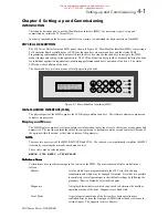
The options available to the user from the main menu are given in Figure 4.3. These options are briefly described
in the following paragraphs which include references for further details.
620 VECTOR
MENU LEVEL
DIAGNOSTICS
SETUP PARAMETERS
SERIAL LINKS
SYSTEM
HEALTH WORD
HEALTH STORE
FIRST ALARM
CHANGE PASSWORD
SOFTWARE
CONFIG I/O
5703 MODE
DUMP MMI - (Tx)
RAMPS
AUX I/O
PASSWORD
ALARM STATUS
MENUS
PARAMETER SAVE
ENTER PASSWORD
UDP XFR - (Tx)
P3 TAG LIST
UDP XFR - (Rx)
P3 BAUD RATE
JOG
INVERSE TIME
STOP RATES
ALARMS
SPEED LOOP
SETPOINT SUM 2
PRESET
RAISE/LOWER
CALIBRATION
CURRENT LOOP
SETPOINT SUM 1
SETPOINT SUM 3
RESERVED
CONFIG DRIVE
HEALTH INHIBIT
BASE FREQUENCY
ENCODER LINES
MAX SPEED RPM
MOTOR VOLTAGE
MOTOR RATING RMS
NO. OF POLES
MAX SPEED RPM
MAG. CURRENT
ENCODER SIGN
START AUTOTUNE
NAMEPLATE RPM
ROTOR TIME CONST
)LJXUH
#716#0#
0DLQ
#
0HQX
#
2SWLRQV
&RQILJXUH
#
'ULYH
&RQILJXUH
#
'ULYH
&RQILJXUH
#
'ULYH
&RQILJXUH
#
'ULYH
The CONFIGURE DRIVE option provides a fast track to commissioning a new 620 Vector drive. It contains all
the parameters necessary for basic operation, grouped together under one menu. This will be described under
‘Setup Step 4’ later in this chapter.
'LDJQRVWLFV
'LDJQRVWLFV
'LDJQRVWLFV
'LDJQRVWLFV
The DIAGNOSTIC option provides the user with access to read-only displays of the various drive status
parameters. Refer to Chapter 5 for further details.
6HW
0
XS
#
3DUDPHWHUV
6HW
0
XS
#
3DUDPHWHUV
6HW
0
XS
#
3DUDPHWHUV
6HW
0
XS
#
3DUDPHWHUV
The SETUP PARAMETERS option provides the user with the facility to adjust and set a large number of drive
parameters. Refer to "SETUP PARAMETERS" in this chapter for further details.
3DVVZRUG
3DVVZRUG
3DVVZRUG
3DVVZRUG
The PASSWORD option allows the user to protect the setup parameters from being changed by an unauthorised
user. Procedures for setting and changing passwords are included in "PASSWORD" in this chapter.
$ODUPV
$ODUPV
$ODUPV
$ODUPV
The ALARMS option provides access to the last alarm message. If the drive trips, the MMI display immediately
shows an alarm message indicating the reason for the trip. This message can be cleared using the ESCAPE key
E
, but can be re displayed via the ALARMS menu. Possible alarm messages are explained in Chapter 5.
0HQXV
0HQXV
0HQXV
0HQXV
The MENUS option allows the user to select the language in which the text appears.
3DUDPHWHU
#
6DYH
3DUDPHWHU
#
6DYH
3DUDPHWHU
#
6DYH
3DUDPHWHU
#
6DYH
The PARAMETER SAVE option enables the user to store the setup parameters after adjustment.
6HULDO
#
/LQNV
6HULDO
#
/LQNV
6HULDO
#
/LQNV
6HULDO
#
/LQNV
The SERIAL LINKS option allows access to the serial link setup parameters which are used to configure the
RS232 port: P3 (fitted as standard).
6\VWHP
6\VWHP
6\VWHP
6\VWHP
The SYSTEM option enables the user to set re configurable input and output control board connections. Refer to
"SYSTEM" for further details.
This manual was downloaded on www.sdsdrives.com
+44 (0)117 938 1800 - [email protected]