)XQFWLRQ
#
%ORFNV
##
8068
953#
9HFWRU
#
'ULYH
#0#
+$
7968;7
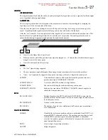
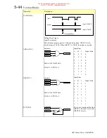
How far does the car travel between the detection of the homing sensor and the drive seeing the command ?
It will be assumed that the drive will be travelling relatively slowly when it receives the home command 1.5Hz
= 0.75 RPM = 15 counts / ms = 0.0825 mm / ms.
Typically the worst case levelling error will therefore be 0.08 * (cycle time of lift cont cycle time of the
vector drive) = 0.08 * (10+10) = 1.6mm.
This can be halved to
±
1mm by adjusting the stopping distance by 1mm.
%/2&.
#
',$*5$0
%/2&.
#
',$*5$0
%/2&.
#
',$*5$0
%/2&.
#
',$*5$0
Home
Home
f(x)
Homing Distance
1/Encoder Scale
Linear O/P
Output
Input
Home Dest
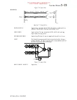
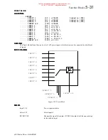
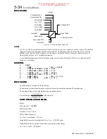
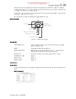
Figure 5.23 Home Block Diagram
3$5$0(7(56
3$5$0(7(56
3$5$0(7(56
3$5$0(7(56
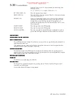
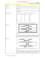
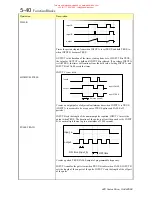
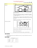
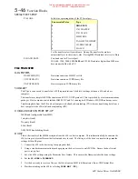
1/ENCODER SCALE
Scalar for homing distance. A value of 4.00 has the effect of converting
encoder counts into “lines”.
HOME
Trigger Input, enables the home function.
HOMING DISTANCE
Homing distance is specified in Encoder Counts * 1 / Encoder Scale, a
2048 line encoder equates to 8192 counts per revolution.
LINEAR O/P
Selects between linear and S velocity profiles, TRUE = Linear.
OVERSHOOT LIMIT
Internal.
HOME INPUT
Diagnostic.
HOME OUTPUT
Diagnostic.
23(5$7256
9$/8(
#
)81&
9$/8(
#
)81&
9$/8(
#
)81&
9$/8(
#
)81&
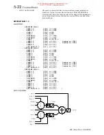
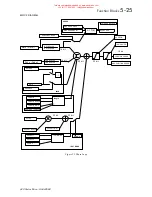
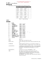
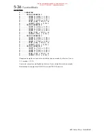
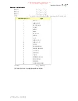
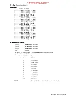
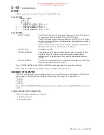
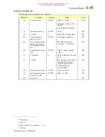
The value function blocks can be configured to perform one of a number of functions upon a fixed number of
inputs.
%/2&.
#
',$*5$0
%/2&.
#
',$*5$0
%/2&.
#
',$*5$0
%/2&.
#
',$*5$0
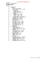
VALUE FUNC 1
OUTPUT
[]
–0.00%
0.00%–
INPUT A
–
0.00%–
INPUT B
–
0.00%–
INPUT C
–
A+B+C–
TYPE
–
This manual was downloaded on www.sdsdrives.com
+44 (0)117 938 1800 - [email protected]


