Hub van Doorneweg 8 • 2171 KZ Sassenheim – NL •
T
+31(0)252 228850 •
F
+31(0)252 228235 •
E
I
euronormdrives.com
6
7
EURN010000_
002_C
EURN010000_
002_C
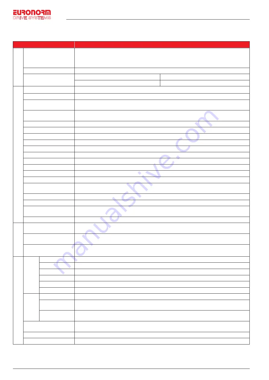
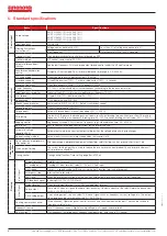
5. Standard specifications
Items
Specifications
Power Input
Rated voltage
AC 1PH 220V(-15%)
~
240V(+10%)
AC 3PH 220V(-15%)
~
240V(+10%)
AC 3PH 380V(-15%)
~
440V(+10%)
AC 3PH 480V(-10%)
~
480V(+10%)
Input frequency
50Hz/60Hz
Allowing fluctuations
fluctuation:±5%;
Voltage continued volatility:±10%
Less than 3% of voltage unbalance rate 3%;
Input frequency
Distortion satisfy IEC61800-2 standard
Contr
ol system
Control system
High performance vector control inverter based on DSP
Control method
V/F control, vector control W/O PG
Automatic torque boost
function
Realize low frequency (1Hz) and large output torque control under the V/F control mode.
Acceleration/deceleration
control
Straight or S-curve mode. Four times available and time range is 0.0~6500.0s.
V/F curve mode
Linear, square root/m-th power, custom V/F curve
Over load capability
G type:Rated current 150% - 1 minute, rated current 180% - 2 seconds
Maximum frequency
1. Vector control:0~300Hz; 2. V/F control:0~3200Hz
Carrier frequency
0.5~16kHz; automatically adjust carrier frequency according to the load characteristics.
Input frequency resolution
Digital setting:0.01Hz minimum analog:Maximum frequency*0.025%.
Start torque
G type: 0.5Hz/150% (Vector control W/O PG)
Speed range
1:100 (Vector control W/O PG)
Steady-speed precision
Vector control W/O PG: ≤± 0.5% (Rated synchronous speed)
Torque response
≤ 40ms (Vector control W/O PG)
Torque boost
Automatic torque boost; manual torque boost(0.1%~30.0%)
DC braking
The built-in PID adjusts the braking current to ensure sufficient braking torque without over-flow.DC braking
frequency: 0.0Hz to max. frequency, braking time:0.0~100.0 seconds, braking current value: 0.0%~100.0%
Jogging control
Jog frequency range: 0.00Hz to max. frequency; jog Ac/deceleration time: 0.0~6500.0s.
Built-in PID
Easy to realize closed-loop control system for the process control.
Automatic voltage
regulation(AVR)
Automatically maintain a constant output voltage when the voltage of electricity grid changes.
Speed tracking method
Automatically track current motor speed when the inverter starts
Personalization
function
Self-inspection of peripherals
after power-on
After powering on, peripheral equipment will perform safety testing, such as ground, short circuit, etc.
Quick current limiting
The current limiting algorithm is used to reduce the inverter over current probability, and improve whole unit
anti-interference capability.
Timing control
Timing control function: Time setting range(0m~6500m)
Running
Input Signal
DI Input terminal
5 digital input terminals
AI1 analog input
1 analog AI1 input terminal, select 0~10V or 0~20mA input
Multi-speed
At most 16-speed can be set(Run by using the multi-function terminals or program)
Emergency stop
Interrupt controller output
Fault reset
When the protection function is active, you can automatically or manually reset the fault condition.
PID feedback signal
Including DC(0~10V), DC(0~20mA)
Output Signal
Output terminal
1 way relay output terminal; 1 way DA1 analog output terminal
Relay output
There are 40 kinds of signals to choose from each way. Contact capacity of the relay: Normally open contact
5A/AC 250V; 5A/DC 30V
DA1 analog output
1 way analog output, you can select 16 kinds of signals such as frequency, current, voltage, etc. The output
signal range can be set arbitrarily within 0~10V/0~20mA.
Running command channel
Three channels: Operation panel, control terminals and serial communication port. They can be switched
through a variety of ways.
Frequency source
Total 7 frequency sources: Digital, analog voltage, multi-speed, and serial port.
Run function
Limit frequency, jump frequency, frequency compensation, auto-tuning, PID control


