EURONORM JI150 Manual Download Page 10

Hub van Doorneweg 8 • 2171 KZ Sassenheim – NL • 

T

 +31(0)252 228850 • 

F

 +31(0)252 228235 • 

E

 [email protected] • 

I

 euronormdrives.com

10

11

EURN010000_

002_C

EURN010000_

002_C

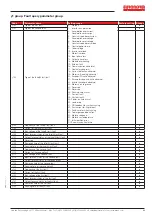
F0 group Basic Functional Parameter Group

Code

Parameter name

Setting range

Factory setting Change

F0.00

Motor control mode

0:  Vector control without PG ;  2:V/F control 

2

F0.01

Keyboard set frequency

0.00Hz~F0.19(Maximum frequency) 

50.00Hz

F0.02

Frequency command resolution 

1:  0.1Hz       
2: 0.01Hz

2

F0.03

Frequency source master setting

0:  Keyboard set frequency (F0.01 ,UP/DOWN can be modified,
  power-down without memory)
1:  Keyboard set frequency (F0.01 ,UP/DOWNcan be modified,
  power-down with memory);
2:  Analog AI1 setting;
4:  Panel potentiometer setting (External keyboard use);
6:  Multi-speed operation setting ;
7:  Simple PLC program setting;
8:  PID control setting;
9:  Remote communications setting

1

F0.04

Frequency source auxiliary setting  Same as F0.03 setting 

0

F0.05

Reference object selection for 
frequency source auxiliary setting 

0.  Relative to maximum frequency;
1.  Relative to master frequency source 1
2.  Relative to master frequency source 2

0

F0.06

Frequency source auxiliary setting 
range

0%~150%

100%

F0.07

Frequency superimposed selection

Units digit: Frequency source selection;
Tens digit: Arithmetic relationship of master and auxiliary for 
frequency soruce

00

F0.08

Auxiliary offset frequency

0.00Hz~F0.19 (Maximum frequency)

0.00Hz

F0.09

Shutdown memory selection

0:  W/O memory;      
1:  With memory

1

F0.10

Frequency command UP/DOWN 
reference when running

0:  Running frequency;    
1:  Set frequency

0

F0.11

Command source selection

Keyboard control (LED off); 
1.  Terminal block control (LED on)
2.  Communications command control (LED flashes)
3.  Keyboard Communications command control
4.  Keyboard Communications command c 
  Terminal block control

0

F0.12

Binding frequency source for 
command source

Units digit: Keyboard command binding frequency source selection 
0:  Not binded;      
1:  Keyboard set frequency;
2:  AI1 setting; 
4:  Panel potentiometer setting (External keyboard)
6:  Multi-speed setting;   
7:  Simple PLC setting; 
8:  PID setting;       
9:  Communications reference
Tens digit: Terminal command binding frequency source selection 
(0~9, same as units digit)
Hundreds digit: Communication command binding frequency source 
selection (0~9, same as units digit)

000

F0.13

Acceleration time1

0.0s~6500s

Depends on 
models

F0.14

Deceleration time1

0.0s~6500s

Depends on 
models

F0.15

Ac/Deceleration time unit 

0: 1s;   1: 0.1s;    2: 0.01s

1

F0.16

Ac/deceleration time reference 
frequency

0:  F0.19 (Maximum frequency)   1:  Set frequency; 
2: 100Hz

0

F0.17

Carrier frequency adjustment 

0:  NO ; 
1: YES 

0

F0.18

Carrier Frequency

0.5kHz~16.0kHz

Depends on 
models

F0.19

Maximum output frequency

50.00Hz~320.00Hz

50.00Hz

F0.20

Upper limit frequency source

0:  F0.21 setting; 

1:  Analog AI1 setting; 

5:  Communications reference

0

F0.21

Upper limit frequency

F0.23 (Lower limit frequency) ~ F0.19 (Maximum frequency)

50.00Hz

F0.22

Upper limit frequency offset

0.00Hz~F0.19 (Maximum frequency)

0.00Hz

F0.23

Lower limit frequency 

0.00Hz~F0.21 (Upper limit frequency ) 

0.00Hz

F0.24

Running direction 

0:  Same direction;  1:  Opposite direction

0

F0.26

AIAnalog accuracy

0:  0.01Hz; 

1:  0.05Hz;   

2:  0.1Hz;  

3:  0.5Hz

1

Summary of Contents for JI150

Page 1: ...www euronormdrives com info euronorm nl 31 0 252 228850 Frequency Drive JI150 Manual...

Page 2: ...terminals 11 F2 group Output terminal 13 F3 group Start and stop control group 14 F4 group V F control parameter group 15 F5 group Vector control parameter group 15 F6 group Keyboard and display 16 F7...

Page 3: ...requency inverter The diagrams of these operating instructions are used for convenience of explanation and may be slightly different from the product due to product upgrades Please take this manual to...

Page 4: ...installation position mm Weight kg L W H A B d E JI150 0R7G4 Z 0 75 138 72 123 5 127 61 5 62 1 1 JI150 1R5G4 Z 1 5 JI150 2R2G4 Z 2 2 JI150 004G4 Z 4 185 72 134 175 45 5 82 1 3 JI150 5R5G4 Z 5 5 0 75 5...

Page 5: ...ance vector control inverter based on DSP Control method V F control vector control W O PG Automatic torque boost function Realize low frequency 1Hz and large output torque control under the V F contr...

Page 6: ...trol Jog frequency range 0 00Hz to max frequency jog Ac deceleration time 0 0 6500 0s Built in PID Easy to realize closed loop control system for the process control Automatic voltage regulation AVR A...

Page 7: ...n At most save three error message and the time type voltage current frequency and work status can be queried when the failure is occurred Key lock and function selection Lock part or all of keys defi...

Page 8: ...wiring requirements correct selection of accessories such as Voltmeter input power supply etc After completing the wiring please check it correctly and make sure that it is correct before powering it...

Page 9: ...put status DO output status d0 09 AI1 voltage AI1 input voltage value 0 01V d0 12 Count value Actual pulse count value in counting function d0 13 Length value Actual length in fixed length function d0...

Page 10: ...nning 0 Running frequency 1 Set frequency 0 F0 11 Command source selection Keyboard control LED off 1 Terminal block control LED on 2 Communications command control LED flashes 3 Keyboard control Comm...

Page 11: ...rminal 1 The setting of 16 stage speed or 16 kinds of other command can be achieved through the 16 states of the four terminals 13 Multi speed terminal 2 14 Multi speed terminal 3 15 Multi speed termi...

Page 12: ...then switches directly to DC braking status 50 Clear current running time If the terminal is valid the inverter s current running time is cleared Table 1 Multi command functions description Over 4 se...

Page 13: ...Ready to run When the inverter main circuit and control circuit power supply has stabilized and the drive does not detect any fault information the drive is in an operational state output ON signal 1...

Page 14: ...Relay 1 output delay time 0 0s 3600 0s 0 0s F2 15 DO terminal active status selection Units digit Reserve Tens digit Relay 0 Positive 1 Negtive 00000 F2 16 DA1 zero bias coefficient 100 0 100 0 20 0...

Page 15: ...00 80 F4 11 V F oscillation suppression gain 0 100 0 F4 12 V F separation voltage source 0 9 0 F4 13 V F separation voltage digital setting 0V motor rated voltage 0V F4 14 V F separation voltage rise...

Page 16: ...F6 06 Inverter module radiator temperature 0 0 100 0 F6 07 Total running time 0h 65535h F6 08 Total power on time 0h 65535h F6 09 Total power consumption 0 65535 F6 10 Product number Inverter product...

Page 17: ...22 Start protection selection 0 OFF 1 ON 0 F7 23 FDT1 detection value 0 00Hz F0 19 Max frequency 50 00Hz F7 24 FDT1 detection hysteresis value 0 0 100 0 FDT1 level 5 0 F7 25 Frequency reaches detectio...

Page 18: ...8 12 Automatic fault reset 0 1s 100 0s 1 0s F8 25 Abnormal reserve frequency 60 0 100 0 100 F8 26 Momentary power cut action selection 0 Invalid 1 Deceleration 2 Deceleration and stop 0 F8 28 Recovery...

Page 19: ...on 1 Compensation mode 1 2 Compensation mode 2 1 Fb 06 Upper limiting frequency for DPWM switching 0 00 15 00Hz 12 00Hz Fb 07 PWM modulation mode 0 Asynchronous 1 Synchronous 0 Fb 08 Random PWM depth...

Page 20: ...2 stage ac deceleration time selection Same to E1 19 0 E1 24 3 stage running time T3 0 0s h 6500 0s h 0 0s h E1 25 3 stage ac deceleration time selection Same to E1 19 0 E1 26 4 stage running time T4...

Page 21: ...l gain KP1 0 0 to 200 0 80 0 E2 14 Integration time Ti1 0 01s to 10 00s 0 50s E2 15 Differential time Td1 0 00s to 10 000s 0 000s E2 16 Proportional gain KP2 0 0 to 200 0 20 0 E2 17 Integration time T...

Page 22: ...rter power 55kW 0 01mH to 655 35mH Inverter power 55kW Motor parameters b0 10 Asynchronous motor no load current 0 01A to b0 03 Inverter power 55kW 0 1A to b0 03 Inverter power 55kW Motor parameters b...

Page 23: ...back loss when running 40 Fast current limiting timeout 41 Switch motor when running 42 Too large speed deviation 43 Motor overspeed 45 Motor over temperature 51 Initial position error COF communicati...

Page 24: ...ens 2 The control mode is vector and without identification of parameters 3 The deceleration time is too short 4 The voltage is low 5 Suddenly increase the load in the process of deceleration 6 didn t...

Page 25: ...he existing problems in the peripheral line 2 replace the drive the power board or contactor 18 Err 18 Current detection fault 1 Check Hall device 2 The drive panel is abnormal 1 Replace the drive pan...

Page 26: ...___________________________________________________________________ ____________________________________________________________________________________________________________________________________...

Page 27: ...Hub van Doorneweg 8 2171 KZ Sassenheim NL T 31 0 252 228850 F 31 0 252 228235 E sales euronorm nl I euronormdrives com 27 EURN010000_002_C Delivery program...

Page 28: ...www euronormdrives com Hub van Doorneweg 8 Sassenheim...

Reviews: