ES5372.1-B 1 Slot Carrier Board for ES4455.2 and ES4456.2 - User’s Guide
28
Setup, Installation and Fuses
ETAS
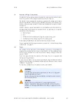
Installing the ES5372.1 Carrier Board in an ES5300.1-A Housing or
ES5300.1-B Housing
1. Ensure that ESD-compliant conditions exist at your
workplace.
2. Shut down the real-time PC and switch off the
power supply of the ES5300.1-A or ES5300.1-B
using the switch at the rear of the housing.
3. Wait at least three minutes for the components
(capacitors, etc.) to be discharged.
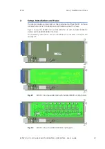
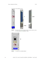
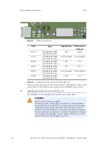
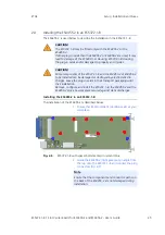
4. Insert the ES5372.1-B (handle at the front plate
with small blue plate must point down!) into the
upper and lower rail of the slot and push it in a little
bit.
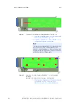
5. Carefully push in the carrier card until the back-
plane connector of the ES5372.1-B is completely
inserted in the socket of the backplane.
6. Fix the carrier card by fastening the front plate with
screws.
CAUTION!
While installing or removing the ES5372.1 Carrier Board into or from
the ES5300.1-A Housing and the ES5300.1-B Housing, observe the
following: Always guide the plug-in cards with both hands. The fitted
cards are heavy and may fall if carried with one hand only.
CAUTION!
The air circulation inside the ES5300.1-A housing and the ES5300.1-B
housing can be ensured only if all free slots are covered with front
plates. Otherwise, it may lead to overtemperatures and trip the over-
temperature protection of the ES5300.1-A or the ES5300.1-B. For
this reason, install front plates in all free slots!
CAUTION!
If cards (e.g. for startup or calibration) are unlocked but not com-
pletely removed from the housing, they must be pulled out far
enough that the distance between the respective card and the back-
plane of the housing is at least 1 cm. Otherwise, contacts may be
established between the cards and lead to their destruction.
Note
Watch for cables in the insert area while pushing the
card in – pull the lines into the front door area if
necessary.
While pushing in the card, ensure that the electrolytic
capacitors of the ES4455.2 are not sheared off.

