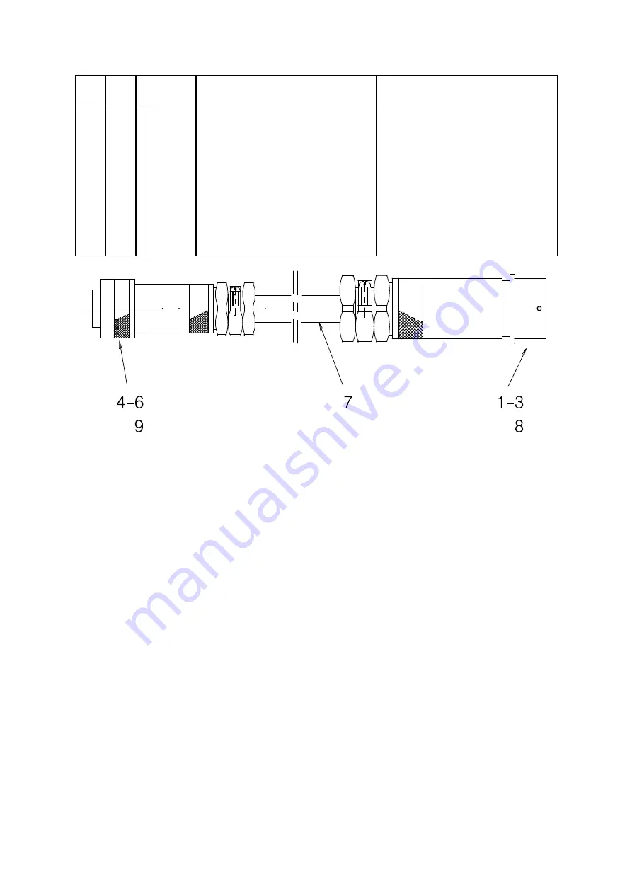
ESAB PEH 4.3 Service Manual Download Page 72

-- 72 --

f449448s

Item

no.

Qty

Ordering no. Denomination

Notes

0449448880

Adapter

28--12POL(PEH--LAF12P)

1

1

0368546106

Sleeve cable socket

28--pol

2

3

0323945003

Connector sleeve

0,52--1,50

3

5

0323945002

Contact sleeve

0,32--0,52

4

1

0368541303

Pin plug burndy

12 pol.

5

5

0323945001

Connector pin

0,32--0,52

6

3

0323945004

Connector pin 0,52--1,50

0,52--1,50

7

1

0193963001

Cable, screened

5x0.5mm2 3x1.5mm2 4x2.5mm2

8

4

0323945007

Contact sleeve

max 2.5mm2

9

4

0323945008

Contact pin

max 2.5mm2

Summary of Contents for PEH 4.3

Page 1: ...from machine no 220 XXX XXXX Valid for program version PEH4 0 PEH4 0C PEH4 01 PEH4 01C PEH4 2 PEH4 2C PEH4 3 PEH4 3C PEH 5 0 PEH5 0C PEH 5 1 and PEH 5 1C 0740 801 106 A2 A6 Process Controller PEH 104...

Page 2: ...ions 23 9 4 Adjusting the DC DUO 25 9 5 NME connection 25 9 6 Connection between the DC DUO and the NME 26 10 USING THE CONTROL PANEL 27 10 1 Control panel 27 10 2 Using the keys 28 11 PRESET SYSTEM M...

Page 3: ...3 TOCe Rights reserved to alter specifications without notice SPARE PARTS LIST 65 ALPHABETICAL LIST OF CONTENTS 73...

Page 4: ...nd or repair This manual contains details of all design changes that have been made up to and including October 2006 This manual is valid for program version PEH4 0 PEH4 01 PEH4 2 PEH 4 3 and PEH 5 0...

Page 5: ...reventing unsafe usage of tacho function From 98 05 20 PEH program Flash IC 15 486471880 PEH 1 2 DCDUO program Prom IC304 68S07001A02 CHKSUM 0221 Dat 1998 04 04 External start stop function Strip weld...

Page 6: ...ion 4 0 digio 4 0 and Analogue Motor node 4 0 From 03 04 14 PEH program Flash IC 15 486471880 PEH 4 01 PEH program China Flash IC 15 486471881 PEH 4 01C DCDUO program Prom IC304 68S07001A02 CHKSUM 022...

Page 7: ...rsion or higher must be used LAF TAF 4 0 digio 4 0 and Analogue Motor node 4 0 From 06 10 01 PEH program Flash IC 15 486471880 PEH 5 0 PEH program china Flash IC 15 486471881 PEH 5 0C DCDUO program Pr...

Page 8: ...ors Improved arc ignition Parallel connection of LAF TAF 800 60 duty factor Complete support for Weldoc Not in the Chinese version Gauging process added Calibration function Not in the Chinese version...

Page 9: ...99 06 01 Digital I O node 486592882 DIG IO 1 1 Safer readings of push buttons preventing unrequested stop during welding From 02 11 15 Digital I O node 486592882 DIG IO 4 0 Safer bus communication wi...

Page 10: ...10 fzb2d1ea GB...

Page 11: ...ion S location of emergency stops S its function S relevant safety precautions S welding 2 The operator must ensure that S no unauthorised person is stationed within the working area of the equipment...

Page 12: ...Use ventilation extraction at the arc or both to take fumes and gases away from your breathing zone and the general area ARC RAYS Can injure eyes and burn skin S Protect your eyes and body Use the cor...

Page 13: ...e supply K5 3 is connected to 5 V K5 4 is connected to 5 V K5 5 is connected to 0 V K5 6 is connected to 0 V K7 Bus termination on NME circuit board K9 Connection of the serial bus connection K10 Conn...

Page 14: ...14 fzb2d2ea 4 CONNECTION DIAGRAM GB...

Page 15: ...15 fzb2d2ea GB...

Page 16: ...16 fzb2d2ea 5 COMPONENT POSITIONS ON CIRCUIT BOARD AP2 GB...

Page 17: ...17 fzb2d2ea 6 COMPONENT POSITIONS ON CIRCUIT BOARD AP1 GB...

Page 18: ...ay be separately excited or of permanent magnet type Speed control is effected either by measurement of the armature voltage or by tachometer control 7 2 NME AP2 This board is built up around an MC 14...

Page 19: ...sured quantities from the power section to voltage levels that allow A D conversion 4 Power section Consists of two full wave MOSFET transistor bridges and associated drive circuits and current shunts...

Page 20: ...oss the following components negative to GND Set value Approved value range Positive connected to K17 1 60 V 53 VDC U 65 VDC Positive connected to K1 1 5 V 4 8 V U 5 2 V Positive connected to cathode...

Page 21: ...width and an amplitude close to 60 V 8 5 Checking NO 2 output stage S Issue a RUN command S Check the voltage on IC407 11 It should normally be low at 0V S Check the waveform on IC409 5 It must be a s...

Page 22: ...ll the cables are screened and the screens must be connected to the earth points intended for them The 12 pole connector XS1 is connected internally to circuit board connectors K13 and K9 and to termi...

Page 23: ...connected to connectors K10 1 and K10 2 with the field connections made to K10 3 and K10 4 The AC tachometer cable accessory is connected to connectors K10 5 and K10 6 Connection of the welding head A...

Page 24: ...emergency stop connection and connect the external emergency stop circuit to X2 2 Input for connection of a gas flow guard NC limit switch or external stop function Screened 2 wire 2 x 0 75 mm2 conne...

Page 25: ...rries a DlP switch SW1 which is preset on delivery for use with A2 A6 units and its settings must not be altered in the field When supplied as a spare part the settings of the switch must be checked a...

Page 26: ...K7 9 6 Connection between the DC DUO and the NME The NME circuit board AP2 is a separate unit that is secured above the DC DUO circuit board AP1 by means of four screws Connectors K3 communication be...

Page 27: ...6 Change menu 7 Numerical key number entry 8 ENTER key Change row 9 SHIFT key 10 Stop welding Return to manual mode 11 Start welding Switch to automatic mode 12 Fast wire feed or travel 13 Scroll pag...

Page 28: ...ange a setting move from Column A to Column B with S Find the required alternative with or with Note that for certain rows you have to enter your own values S Return to Column A with S Move forward to...

Page 29: ...formation on gear ratios motor types drive rollers diameters etc For information about the Control panel and information about how to use the keys see pages 27 28 11 2 System function settings availab...

Page 30: ...machine S A6TGE A6 MIG MAG automatic welding machine S FREE2AX Optional configuration for connection of two motors to the drive board S FREE3AX Optional configuration for connection of external Roller...

Page 31: ...1 750 1 24 1 24 1 375 2 375 2 Gear2 158 100 158 100 51 1 51 1 427 100 427 100 P D mm 158 158 158 158 180 180 Encoder ppr 0 0 6 6 0 0 Low manual speed 100 100 100 100 100 100 High manual speed 200 200...

Page 32: ...or FHP36 FHP68 FHP258 VEC8000 VEC4000 DUNKER1 DUNKER2 MET3B PEH 4 0 PEH4 01 VEC4000Par PEH 4 2 PEH4 3 GEAR 1 GEAR 2 P D mm 1 10000 Encoder ppr 0 10000 Low manual speed 1 1000 High manual speed 1 5000...

Page 33: ...has been selected N1 X N2 X By entering values for N1 and N2 any gear ratio located after the motor gears for example FHP 36 can be selected N1 the number of teeth of the gear wheel of the motor shaft...

Page 34: ...ust be bridged S Limit switch Limit switches normally with closed NC contact function are to be connected to the inputs When one of the limit switches is activated opened the motion of the motor cease...

Page 35: ...ll differ from those of the Preset Values Set your own offset values for the wire feed motor M1 VXPoffset 32768 and for the travel motor M2 VYPoffset 32768 Example How to adjust the offset error of th...

Page 36: ...8 Negative voltage offset travel motor CYPoffset 32768 Positive current offset travel motor CYNoffset 32768 Negative current offset travel motor VXPscale 19200 Positive armature voltage measurement sp...

Page 37: ...near axis LIN settings must be made in FREE3AX To steer ROL POS or LIN the analogue PCB card must be connected The PCB gives a reference signal of 0 10V and two direction signals right and left 1 PEH...

Page 38: ...tio High manual speed 1 5000 Available settings for POS GEAR 1 GEAR 2 GEAR 3 Encoder ppr 0 10000 Motor rpm Frequency ratio High manual speed 1 5000 GEAR1 GEAR2 and GEAR3 see on page 33 P D mm is the e...

Page 39: ...ithout an RCC unit press to select an axis LINEAR CIRCULAR The axis activated is presented here PEH 4 0 PEH 4 0 LINEAR Boom or carriage LINEAR1 Boom LINEAR2 Carriage CIRCULAR Roller bed Positioner POS...

Page 40: ...G WIRE DATA Regulation CA PRESET SYSTEM MENU Weld_diameter Roller_diameter Weld joint Weld diameter Roller bed Roller diameter PRESET SYSTEM MENU when setting Positioner Direction Y Start Direct STOP...

Page 41: ...RCE MENU Gas preflow s 1 99 Gas postflow s 1 99 Password XXX Cable length m X Cable area mm2 X The following alternatives can be selected S SAW for submerged arc welding S GMAW for gas metal arc weldi...

Page 42: ...or program version 4 2 4 3 and 5 0 Power source type LAF TAF Other None Power source Wire Creep Speed Max weld voltage dv Min weld voltage dv Max ref voltage mV See on page 42 See on page 43 See on pa...

Page 43: ...e Start Stop Example Max requested reference voltage is 0 5 V write 5000 in the menu The lowest requested weld voltage is 15 V write 150 in the menu Max requested weld voltage is 50 V write 500 in the...

Page 44: ...The Master control box is number 1 PEH1 and the Slave control box is number 2 PEH2 Travel motion is always steered from PEH1 System1 PEH1 and Welding power source no 1 System2 PEH2 and Welding power s...

Page 45: ...stem2 stops welding when it has reached the point where System1 stopped welding the distance is set in Weldhead offset S The weld is finished Example 2 When using a remote control box RCC the two syst...

Page 46: ...tart for Welding power source 2 on the RCC System1 starts to move and System2 starts to weld S Press stop for Welding power source 1 system2 continues welding start welding power source 1 and both sys...

Page 47: ...econds into the selected field Times between 1 and 99 seconds can be entered The default value is 1 second 12 5 Gas postflow s only for GMAW Product code A2TFH Weld process SAW POWER SOURCE MENU Gas p...

Page 48: ...otected by entering a password in the Password field The password must consist of not more than five numerals XXXXX If no password is required enter the numerical value 0 If the password consists of m...

Page 49: ...that occurs in long cables can be compensated for by entering the exact length of the cable being used The total length of the cable in metres welding current and return current cables together must b...

Page 50: ...setting the distance Offset between welding head no 1 and welding head no 2 the distance is converted by the PEH to a time between the start of welding head no 1 and the start of welding head no 2 Th...

Page 51: ...or materials it can be necessary to make up a special start sequence The start method can also influence the appearance of the weld bead The start sequence is divided into two phases PHASE1 and PHASE...

Page 52: ...voltage and speed are adjusted by indicating a percentage value of the welding parameters on the main menu Max adjustable value is 150 as long as the capacity of the welding power source and the max...

Page 53: ...been selected STOP PHASE 1 STOP PHASE 2 The stop sequence menu is mainly used for programming the crater filling It is programmed in the same way as the start sequence menu In the stop sequence menu...

Page 54: ...voltage and speed are adjusted by indicating a percentage value of the welding parameters on the main menu Max adjustable value is 150 as long as the capacity of the welding power source and the max p...

Page 55: ...the PEH display expressed as a percentage of the desired voltage reference value Current at head Shows how many per cent the set reference value constitutes of the measured current value at the weldin...

Page 56: ...ing the CALIBRATION MENU make sure all connectors are properly fitted IMPORTANT S In order not to affect the voltage answer through inductance the voltage reference cable shall not be laid together wi...

Page 57: ...inches Current display Set value Real value The welding parameters can be displayed as either set values or real values The set values are stable and are not subject to rapid fluctuations On the othe...

Page 58: ...58 fzb2d3ea Example How to select the unit Metric S Select Unit and press S Find Metric by pressing S Return to the MAIN MENU with The unit has now been set to Metric GB...

Page 59: ...Incorrect entry of numerical values If incorrect numerical values are entered e g for voltage current or speed a message is generated indicating the values that are allowed Error messages shown on th...

Page 60: ...and then check the heat dissi pating element Welding power source T1 111 01 Communication error Stop Check cables and connections 111 53 Unsuccessful start Stop Check stick out and welding parameters...

Page 61: ...den Test 0 The function is not active Test 1 Wire feed speed is shown in the MAIN MENU according to the figure below This is Not deactivated when the power is off Wire feed speed cm min Test 2 Speed a...

Page 62: ...Gas postflow s Cable area mm2 Cable length m START SEQUENCE MENU Weldhead offset mm START PHASE 1 START PHASE 2 STOP SEQUENCE MENU DISPLAY MENU STOP PHASE 1 STOP PHASE 2 Unit Current display Heat inp...

Page 63: ...he program versions are compatible between for example the PEH and the welding power source 14 2 Storing trimming data Trimming data to the welding power source S Press Trimming data are sent from the...

Page 64: ...source S Store trimming data in the welding power source see Trimming data to the welding power source on page 63 S Replace the flash memory IC15 on the NME card AP2 S Recall trimming data from the w...

Page 65: ...re A2 A6 Process Controller PEH Edition 2004 12 17 Ordering no Denomination Notes 0443 741 880 Control box A2 A6 Process Controller PEH Abbreviations used in the spare parts list C Component designati...

Page 66: ...rgency stop ST1 8 2 0457278001 Rail 9 1 0443748880 Cable complete XS1 10 0443730880 Circuit board AP1 AP2 14 1 0443849001 Insulation 20 1 0449130001 Display ccfl backlight DY1 21 0192526003 Sealing st...

Page 67: ...Cable with connectors 1 1 0368 543 003 Pin socket Burndy 4 1 0443 841 880 Cable set 6 1 0456 489 005 Circuit board connection 7 1 0456 489 004 Circuit board connection 8 1 0193 275 002 Connection bloc...

Page 68: ...0 Circuit board AP1 AP2 2 0456 489 002 Connection terminal 6 poles K10 K11 3 0456 489 001 Connection terminal 2 poles K12 K17 K22 K23 4 0456 489 004 Connection terminal 2 poles K13 K14 5 1 0486 471 88...

Page 69: ...2 Control cable L 35 m Accessories 1 1 0449449882 Control cable 35m 12 28 pole LAF TAF PEH 2 1 0449448880 Adapter 28 12pol PEH LAF 12p 0456500883 Control cable L 50 m Accessories 1 1 0449449883 Contro...

Page 70: ...8 pol 2 3 0323945004 Connector pin 0 52 1 50 3 5 0323945001 Connector pin 0 32 0 52 4 1 0368542303 Sleeve plug burndy 12 pol 5 5 0323945002 Contact sleeve 0 32 0 52 6 3 0323945003 Connector sleeve 0 5...

Page 71: ...pol 2 3 0323945004 Connector pin 0 52 1 50 3 5 0323945001 Connector pin 0 32 0 52 4 1 0368542303 Sleeve plug burndy 12 pol 5 5 0323945002 Contact sleeve 0 32 0 52 6 3 0323945003 Connector sleeve 0 52...

Page 72: ...0323945003 Connector sleeve 0 52 1 50 3 5 0323945002 Contact sleeve 0 32 0 52 4 1 0368541303 Pin plug burndy 12 pol 5 5 0323945001 Connector pin 0 32 0 52 6 3 0323945004 Connector pin 0 52 1 50 0 52...

Page 73: ...R LIST 59 Error message 59 EXTERNAL AXIS 38 External emergency stop 24 F Flash memory IC15 25 G Gas flow guard 13 24 Gas postflow 47 Gas preflow 47 Gas valve 13 24 H Heat input 57 L LED L02 RED 25 Lin...

Page 74: ...2 22 ESAB international AB Gothenburg Tel 46 31 50 90 00 Fax 46 31 50 93 60 SWITZERLAND ESAB AG Dietikon Tel 41 1 741 25 25 Fax 41 1 740 30 55 North and South America ARGENTINA CONARCO Buenos Aires Te...

Reviews: