EPSON Stylus C87/C88/D88
Revision A
DISASSEMBLY/ASSEMBLY
Dissasembly Procedures
73
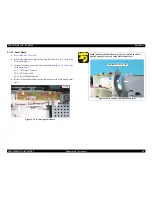
4.3.3.12 PW Sensor Board
1) Remove the CR Unit. (p70)
2) Remove the PW Sensor Cover.
(See 4.3.3.11 Removing Printhead Assy.
Step 2)
3) Disconnect the PW Sensor FFC, and remove the PW Sensor Board.
Figure 4-71. Removing PW Sensor Board
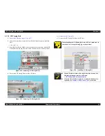
4.3.3.13 CR Encoder Sensor Board
1) Remove the CR Unit. (p70)
2) Disconnect the CR Encoder Sensor FFC and the PW Sensor FFC from the CR
Encoder Sensor Board.
3) Remove the two screws that secure the CR Encoder Sensor Board to the IC
Holder, and remove the CR Encoder Sensor Board.
•C.P.B. (P1) 1.7 x 5:2
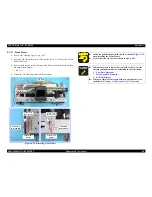
Figure 4-72. Removing CR Encoder Sensor Board
A D J U S T M E N T
R E Q U I R E D
When replacing or removing the PW Sensor Board, make sure to
perform the following adjustments in the order shown below.
1.
Top Margin Adjustment
2.
PF Adjustment
3.
Bi-D Adjustment
4.
Head Angular Adjustment
5.
First Dot Adjustment
6.
PW Sensor adjustment
Bottom
PW Sensor Board
PW Sensor FFC
When installing the CR Encoder Sensor Board, match the
positioning hole with the rib as shown in
Figure 4-72
.
The PW Sensor FFC should be attached to the location with
double-sided tape as shown in
Figure 4-72
.
A D J U S T M E N T
R E Q U I R E D
After replacing or removing the CR Encoder Sensor Board, make
sure to perform the following adjustments.
1.
Top Margin Adjustment
2.
PF Adjustment
3.
Bi-D Adjustment
4.
Head Angular Adjustment
5.
First Dot Adjustment
6.
PW Sensor adjustment
C.P.B. (p1) 1.7 x 5
Rear Side
Positioning Hole
and Guide Pin
CR Encoder
Sensor Board
CR Encoder
Sensor FFC
Double-sided
Tape Location
Summary of Contents for Stylus C87
Page 1: ...EPSONStylusC87 C88 D88 Color Inkjet Printer SEIJ05 002 SERVICE MANUAL ...
Page 5: ...Revision Status Revision Date of Issue Description A August 1 2005 First Release ...
Page 8: ...C H A P T E R 1 PRODUCTDESCRIPTION ...
Page 23: ...C H A P T E R 2 OPERATINGPRINCIPLES ...
Page 29: ...I C H A P T E R 3 TROUBLESHOOTING ...
Page 36: ...C H A P T E R 4 DISASSEMBLY ASSEMBLY ...
Page 80: ...C H A P T E R 5 ADJUSTMENT ...
Page 92: ...C H A P T E R 6 MAINTENANCE ...
Page 98: ...C H A P T E R 7 APPENDIX ...
Page 100: ...104 PX V630 EPSON Stylus C88 D88 D88 Photo Edition C87 No 1 Rev 01 C617 ACCE 001 400 ...
Page 102: ...PX V630 EPSON Stylus C88 D88 D88 Photo Edition C87 No 3 B A Rev 01 C617 ELEC 001 300 200 ...
Page 107: ...Model PX V630 Stylus C87 C88 D88 Board C528 MAIN Rev M Sheet 1 1 ...
Page 108: ...Model PX V630 Stylus C87 C88 D88 Board C528 PSH Rev A Sheet 1 1 ...
Page 109: ...Model PX V630 Stylus C87 C88 D88 Board C528 PNL Rev A Sheet 1 1 ...


