49
p
aneL
anD
m
eDia
i
nstaLLation
:
1. Remove the safety screen and glass door
2. If you are installing 50-3331 (Light Kit) Remove the burner tray now using a T-20 Torx screwdriver;
refer to
s
econDary
I
nstallatIon
- l
Ight
K
It
I
nstallatIon
or see instruction sheet included with the kit.
Install perforated burner tray once lights are installed.
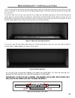
3. Place your burner media into the burner pan (vermiculite or glass media). Create a thin layer that
evenly covers the entire burner pan; pat it down gently.
If flame looks uneven with overly high or
low sections the media can be adjusted. If flame is too high make media thicker, if low thin
media out�
WARNING: Be sure there is no media in the protected pilot area of the
burner pan.
Secondary Installation
b
ezeL
i
nstaLLation
:
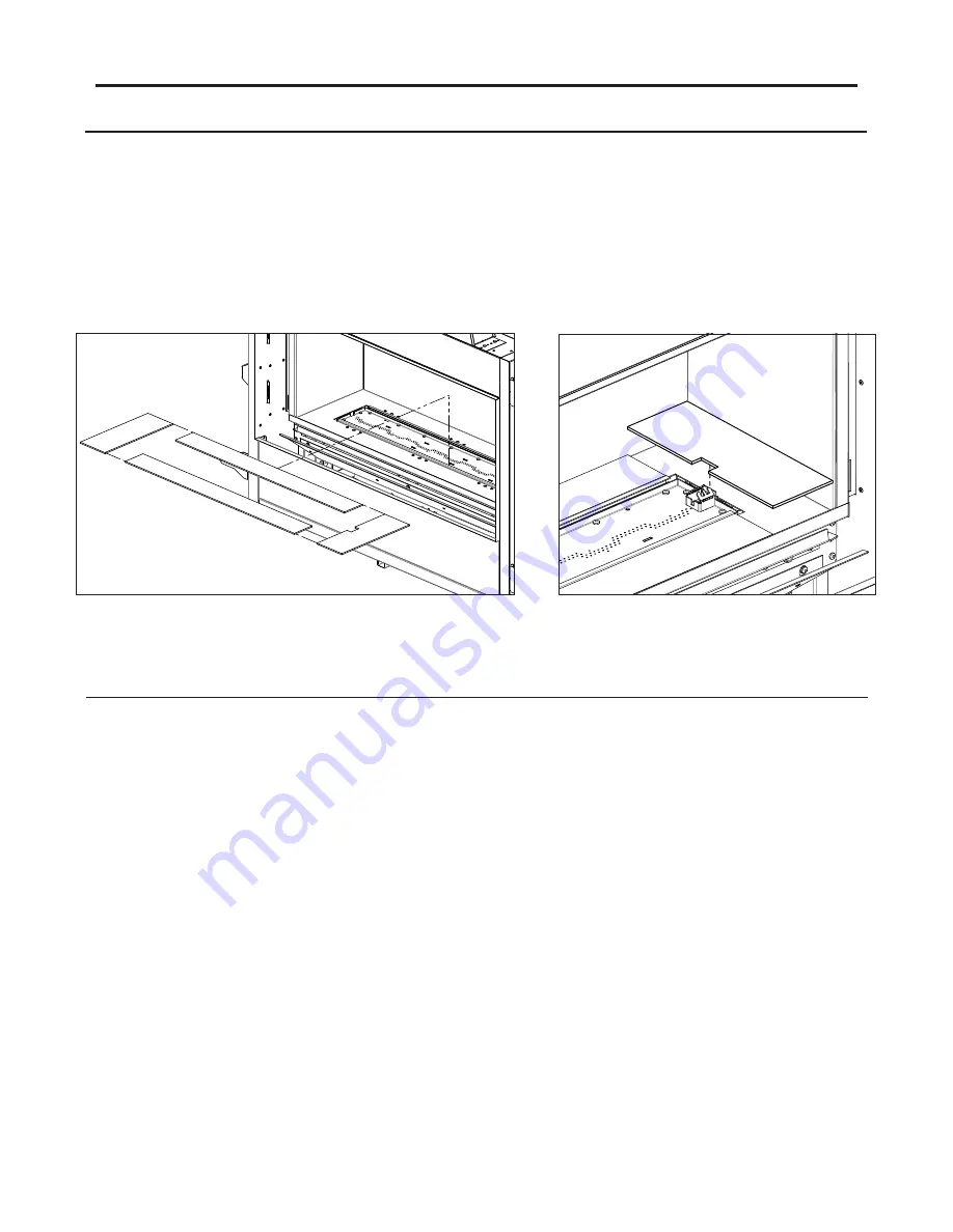
The unit comes with a set of burner bezels. There are two long bezels, one short, and one short with a
notch cutout.
1. Remove the safety screen and glass door
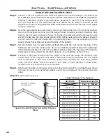
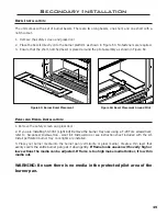
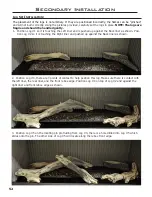
2. Place the bezels directly onto the burner platform as shown in Figure 63. No fasteners are required.
3. Ensure that the short, notched bezel is placed around the pilot assembly as shown in Figure 64.
Figure 63: Burner Bezel Placement
Figure 64: Bezel Placement Around Pilot
Summary of Contents for C34I
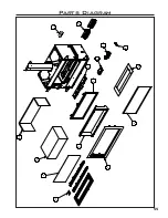
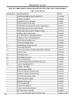
Page 55: ...55 Parts Diagram 1 2 3 5 4 10 8 7 9 12 13 14 6 11 15 ...
Page 57: ...57 Notes ...
Page 58: ...58 Notes ...

