17
Maintenance And Service
b
uRneR
R
emoVaL
:
The burner will need to be removed to maintenance and fuel conversion. Follow the procedure carefully.
Proceed only when the unit has completely cooled down.
1. Remove the safety screen as shown in
m
aIntenance
anD
s
erVIce
- s
afety
s
creen
r
emoVal
.
2. Remove the glass door as shown in the
m
aIntenance
anD
s
erVIce
- g
lass
D
oor
r
emoVal
.
3.
Remove log set or high definition rock set (if installed).
4. Remove any media from the media tray.
5. Remove the media tray as shown in
s
econDary
I
nstallatIon
- m
eDIa
t
ray
r
emoVal
.
6.
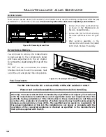
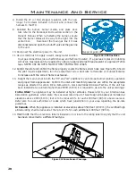
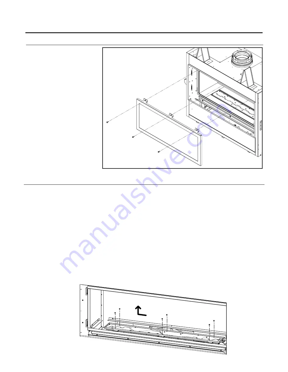
Remove the six T-20 screws securing the burner pan as shown in Figure 19; do NOT remove the other
T-20 screws. Once the specified screws are removed slide burner to the left and lift out to remove.
To re-install the burner follow steps above in reverse. When placing the burner back in the unit be sure not
to move the air shutter.
Make sure the burner is slid all the way in or the mounting holes will not
line up. Do not over tighten the burner screws or they might strip; just get them snug.
g
Lass
D
ooR
R
emoVaL
:
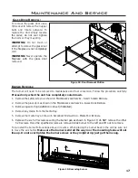
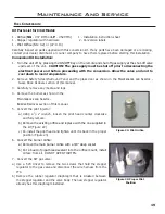
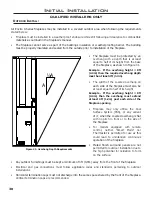
To remove the glass door use a
3/8 socket to remove the 3 upper
bolts and rotate outward. To
replace the door simply reverse
the order; do not over tighten
the bolts or they may strip.
WARNING: Do not touch or
attempt to remove the glass door
if the fireplace is not completely
cold.
WARNING: Never operate the
fireplace with the glass door
removed.
Figure 18:
Door Removal Motion
Figure 19: Removing Burner
Summary of Contents for C34I
Page 55: ...55 Parts Diagram 1 2 3 5 4 10 8 7 9 12 13 14 6 11 15 ...
Page 57: ...57 Notes ...
Page 58: ...58 Notes ...

