25/34
TEC/TEM owner manual
4.
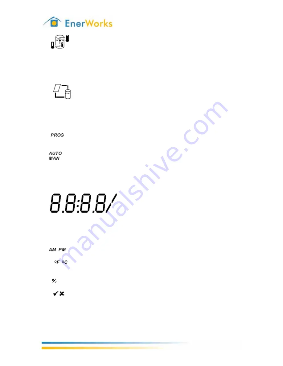
- Tank status. The thermometer on the left represents the incoming
temperature of the mains water. The interior thermometer represents the
temperature of the storage. The thermometer on the right represents the
outgoing temperature of the heated water. The arrow inside the tank blinks
when there is a draw on the tank.
5.
- Pump status. Heat-transfer fluid-lines are represented by
horizontal/vertical lines running between collector and tank. The four lines blink
clockwise when the pump is running, i.e. from the bottom of the tank to the
collector, then from the collector to the top of the tank. The four lines don’t
show when the pump isn’t running.
6.
- Programming mode. Indicates that the Thermal Energy Controller is
in programming mode.
7.
- Pump setting. AUTO means automatic mode, as in the pump will run
based on the logic of temperature differential control (
∆
T, max/min
temperatures, etc.). MAN means that the pump is in manual mode, either
turned on manually (runs for 15 minutes before defaulting back to automatic
mode) or turned off manually and stays off until manually turned back on.
8.
- Seven-segment digits plus decimals, colon, and
slash. The four digits are used to display input/output values along with the
decimals. The colon is only used for displaying the time. The slash is used
when setting the fuel price and the amount of water needed to generate
electricity.
9.
- AM/PM. Used for displaying the 12-hour clock.
10.
- Temperature units. Metric and imperial units for displaying
temperature.
11. - Percentage. Used for setting generation mix of electricity.
12.
- Checkmark and x-mark. These symbols are used in various ways
together, typically meaning on/off, enable/disable, and so forth.


