background image

ENGLISH

11

• Remove 

circlips (24) reaction rollers 

(25) and roller pin (26).

• 

Clean all exposed components with a 
mild solvent.

• 

Inspect all parts for damage.

• 

Dry all components. Apply a thin coat 
of molybdenum disulphide lubricant 

 as indicated.

5.2.2 The hydraulic drive unit 

• 

Check tightness of swivel manifold 
post retaining screws (see 5.3.2) and 
gland.

• 

Pressurize the drive unit to maximum 
pressure (

Advance

 and 

Retract

), and 

check for any signs of leakage.

• 

Any damaged components or seals 
must be replaced.

• 

Dry all components and apply a 
thin coat of molybdenum disulphide 
lubricant 

 as indicated.

5.3 Full 

maintenance


Note:

 Refer to the WCR4000 repair 

parts sheet for detailed views of 
components and subassemblies 
referenced in sections 5.3.1 and 5.3.2.

5.3.1 The roller cassette

• 

Strip down and clean all exposed 
components with a mild solvent.

• 

Drift out the spring pin holding the 
cylinder retaining pin, and remove the 
retaining pin.

• 

Inspect all parts for damage.

• 

Perform non destructive testing by 
magnetic particle inspection on the 
following components:
-  Sideplates
-  Cylinder locating plate
-  Cylinder retaining pin
-  Reaction roller bracket and pin
-  Reaction rollers and roller pin

• 

Dry all components. Apply a thin coat 
of molybdenum disulphide lubricant

 as indicated.

• 

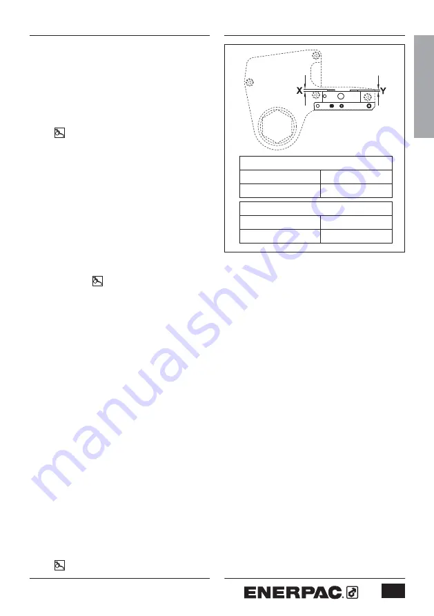
Check retaining pin height (X) and fail 
safe pin height (Y). Refer to Fig. P.

• 

Reverse the procedure to reassemble 
the tool.

5.3.2 The hydraulic drive unit

• 

Remove the circlip from the swivel 
manifold block.

• Remove 

the 

hydraulic couplings.

• Remove 

the 

swivel manifold block 

from the drive unit.

• Remove 

the retaining screws and the 

swivel manifold post.

• 

Remove all ‘O’ rings from swivel 
manifold post.

• 

Carefully hold the cylinder body to 
unscrew the cylinder gland.

• 

Hold the two flat sides of the piston 
rod with a spanner. The rod is located 
at the spigot.

• 

Remove the button head cap screw 
from the piston.

• 

Remove the piston rod from the 
cylinder spigot end.

• 

Remove the piston from the cylinder 
gland end, using a suitable drift.

Retaining Pin Height - Dimension “X”

Metric

Imperial

5,00 mm

0.197 inch

Fail Safe Pin Height - Dimension “Y”

Metric

Imperial

3,00 mm

0.118 inch

Fig. P

Summary of Contents for WCR4000

Page 1: ...Instruction Sheet WCR4000 Roller Cassette L4021 English GB Rev B 09 2013...

Page 2: ...2...

Page 3: ...4 2 Safety 4 3 Assembly and adjustments 6 4 Operation 8 5 Maintenance and troubleshooting 10 6 Technical specifications and torque settings 13 7 Replacement parts and recommended tools 16 Instruction...

Page 4: ...pipe flange Keep the hoses away from this area to prevent them from becoming pinched or crushed 4 ENGLISH 1 Introduction Overview The Enerpac WCR4000 roller cassette provides controlled tightening an...

Page 5: ...operation of the tool may become a high velocity projectile When the spanner is placed on the nut or bolt a gap may exist between the reaction roller and the pipe flange When the tool is operated the...

Page 6: ...needed 3 2 2 To remove the cassette fig D Make sure the piston is fully retracted Hold the tool with the drive unit pointing upwards Swing the reaction roller bracket 8 inward toward center of tool P...

Page 7: ...to the table below Hose model number Description THQ 706T Two hoses length 6 m 19 5 feet THQ 712T Two hoses length 12 m 39 feet Remove the hose dust caps Connect the hose with the female coupling 15...

Page 8: ...tighten a nut or bolt fig G H I Place the wrench on the ground or on a solid surface such as a workbench Operate the pump in the Retract direction until drive unit is fully retracted and the spanner s...

Page 9: ...kwise side of wrench To loosen the nut bolt follow steps in section 4 3 1 but with the counter clockwise side of wrench facing upward Repeat steps until nut bolt is loose If the nut or bolt will be re...

Page 10: ...et screw hole in spanner Apply a small amount of Loctite 243 to threads of set screw 17 Reinstall set screw 17 5 2 Preventative maintenance Fig N O Preventative maintenance can be carried out by the u...

Page 11: ...rform non destructive testing by magnetic particle inspection on the following components Sideplates Cylinder locating plate Cylinder retaining pin Reaction roller bracket and pin Reaction rollers and...

Page 12: ...lbs 5 4 Troubleshooting 5 4 1 Drive Unit Symptom Cause Remedy Cylinder does not advance or retract Quick connect coupling Replace the coupling is damaged Quick connect coupling is Reconnect the hoses...

Page 13: ...0 psi 10 000 Max torque at 690 bar Nm 5 762 at 10 000 psi Ft lbs 4 250 Min torque Nm 576 Ft lbs 425 Dimensions A mm inch 226 8 9 B mm inch 161 6 3 C mm inch 159 6 25 D mm inch 241 9 5 E mm inch 131 5...

Page 14: ...2 9 16 1 81 1 18 4 5 W4212CS 2 3 4 1 93 1 18 4 9 W4215CS 2 15 16 2 05 1 18 4 5 W4302CS 3 1 8 2 17 1 18 4 9 6 2 Technical Data Closed End Spanners fig R 6 2 1 Metric system table Spanner F G H Weight M...

Page 15: ...gs To set the torque adjust the pump pressure according to the following calculation Pump pressure Torque Torque factor Measurement system Torque factor Metric 8 351 Imperial 0 425 6 3 2 Imperial syst...

Page 16: ...nch model and serial numbers for both drive unit and cassette Approximate date of purchase Part number and description of each part being ordered 7 2 Recommended tools for performing maintenance and r...

Page 17: ...17 NOTES...

Page 18: ...18 NOTES...

Page 19: ...19 NOTES...

Page 20: ...wan Actuant Asia Pte Ltd 83 Joo Koon Circle Singapore 629109 T 65 68 63 0611 F 65 64 84 5669 Toll Free 1800 363 7722 sales sg enerpac com South Korea Actuant Korea Ltd 3Ba 717 Shihwa Industrial Comple...

Reviews: