


___________________________________________________________________________________________________
_________________________________________________________________________________________
Page 22 / 30 EZM7750_ENG_VER11
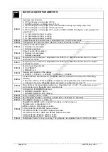
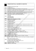
FREQUENCYMETER and TACHOMETER PARAMETERS:
PRO-03
Configuration for measurement method.
0- Counts per turn
1- Counts per time period.
PRO-04
Contact Bounce for electrical noise. Adjustable from 0 to 250 miliseconds.
PRO-07
This parameter is used when PRO-03=0 (counts per turn method). “Time-out” period can be set by
this parameter (1 to 99 seconds). Actual counting value display will be have "000000" value if
elapsed time is greater than the value is set in this parameter.
PRO-08
Measuring Period: This parameter is used when PRO-03=1 (counts per time period method). The
time period for measurement can be set by this parameter (PRO-08=00.0 to 99.9 seconds).
PRO-09
Out-1 Function: 0- Latched; 1- Non-latched with hysteresis; 2- Alarm out
PRO-10
Out-2 Function: 0- Latched; 1- Non-latched with hysteresis
PRO-11
Output-1 Alarm Functions (If Pro-09=2 this parameter is active)
0-High alarm
1-Low alarm
2-High deviation alarm
3-Low deviation alarm
4-Deviation band alarm
PRO-12
Hysteresis for Out-1; Adjustable from 0 to 50000.
PRO-13
Hysteresis for Out-2; Adjustable from 0 to 50000.
PRO-14
Output Function for module-1
0- Normally non-energised
1- Normally energised
PRO-15
Output Function for module-2
0- Normally non-energised
1- Normally energised
PRO-16
Energising time for Module-1. Adjustable from 0000.00 to 0099.99 seconds. Refer to “Output
Functions” for detail.
PRO-17
Energising time for Module-2. Adjustable from 0000.00 to 0099.99 seconds. Refer to “Output
Functions” for detail.
PRO-18
Configuration for enabling the output functions;
0-When the unit is energized. (Power-up)
1-When the measured value reaches the SV1 value.
2-When the measured value reaches the Sv2 value.
PRO-20
Decimal point position of the display.
0 - 000000, 1 – 00000.0, 2 - 0000.00, 3 - 000.000, 4 - 00.0000
PRO-23
Slave Address for serial communication bus. Adjustable from 1 to 247.
The parameter value is “1” for single device on the serial communication bus.
PRO-24
Configuration for MODBUS protocol.
0- MODBUS protocol is ASCII .
1- MODBUS protocol is RTU (Binary) .
PRO-25
Parity; 0-None, 1-Even, 2-Odd
PRO-26
Baud Rate; 0-1200 Bps , 1-2400 Bps, 2-4800 Bps, 3-9600 Bps, 4-19200 Bps
PRO-27
Stop Bits; 0- 1 Stop bit, 1- 2 Stop bit
PRO-28
Protection for RESET, SET-1 and SET-2 buttons on the front panel. The parameter is adjustable 0
to 5.
0-Non protection. All buttons are active.
1-Only protection for RESET button is active.
2-Protection for SET1 and SET2 buttons are active.
3-Protection for SET1, SET2 and RESET buttons are active.
4-Only protection for SET1 button is active.
5-Only protection for SET2 button is active.
PRO-29
Coefficient-1; (1 to 9999)
PRO-30
Coefficient-2; (1.000 to 99.9999)
1
2
3
ON
OFF