


5 – 35
Section 5 • Maintenance/Service
VSS/VSM/VSH/VSSH • Installation, Operation and Maintenance Manual • Emerson • 35391SD
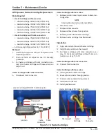
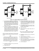
Main Rotor Bearing Axial Clearance Inspection
To inspect bearing axial clearance, proceed with the fol-
lowing steps:
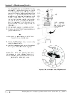
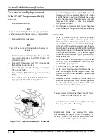
1. Remove center member, see appropriate Drive
Coupling Replacement procedure.
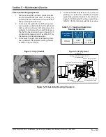
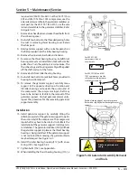
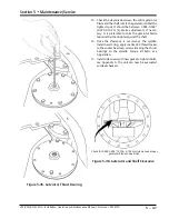
2. Install dial indicator to the compressor frame and
zero indicator, see Figure 5-27.
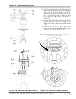
3.
Place lever arm and fulcrum behind compressor
coupling half and push the coupling towards the
motor. Record measurement.
4. Re-zero indicator, now position the fulcrum on the
motor and use the lever arm to push the input shaft
towards the compressor. Record measurement
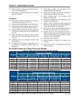
5. Add both measurements. If measurement is out
of allowable tolerance shown in Table 5-10, the
bearing may need to be replaced. Contact Vilter
TM
Technical Support.
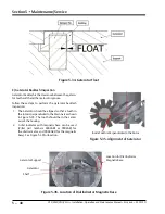
Top View
Small wooden block or fulcrum.
Direction of
shaft movement.
Shaft being pushed by use of lever.
Applied Force
Rigidly attach dial indicator.
Position on axis of compressor.
Top View
Wooden block
or fulcrum
Direction of
shaft movement.
Rigidly attach dial indicator.
Position on axis of compressor.
Applied Force
Shaft being pushed by use of lever.
Figure 5-27. Bearing Axial Clearance
Inspection
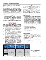
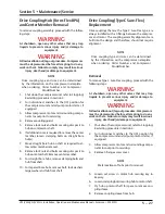
Compressor Inspection
Compressor Shaft Bearing Clearance
Inspections
If clearance measurements are out of tolerance, contact
Vilter Technical Support for further assistance.
CAUTION
When taking the measurements, do not exceed
300 to 500 lbs of force at point of contact or
damage may result to the bearings.
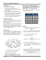
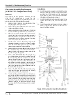
Determine Maximum Applied Force
To determine maximum applied force, take maximum
applied force at hub/shaft multiplied by length of A
and divide by length B. This is the maximum force that
should be applied on the lever.
(Applied Force x A)/B = Applied Force (Maximum)
So, using a 36” (or 1 m) lever with pivot space of 6” (or
15 cm) would make the maximum applied force to be 60
lbf (or 235 N). Calculation is as follows:
(300 lbf x 6”)/30” = 60 lbf (Max.
Applied Force
)
(1335 N x 15 cm)/85 cm = 235 N (Max.
Applied Force
)
B
A
Lever
Wooden Block
or Fulcrum
Applied
Force
Force at
Hub/Shaft
Pivot Point
As a quick reference, Table 5-10 shows maximum ap-
plied forces for 36” lever with 6” pivot for all compres-
sor models.
Summary of Contents for Vilter VSH
Page 2: ......
Page 30: ...2 4 Blank VSS VSM VSH VSSH Installation Operation and Maintenance Manual Emerson 35391SD ...
Page 54: ...3 24 Blank VSS VSM VSH VSSH Installation Operation and Maintenance Manual Emerson 35391SD ...
Page 74: ...4 20 Blank VSS VSM VSH VSSH Installation Operation and Maintenance Manual Emerson 35391SD ...
Page 144: ...5 70 Blank VSS VSM VSH VSSH Installation Operation and Maintenance Manual Emerson 35391SD ...
Page 156: ...7 4 Blank VSS VSM VSH VSSH Installation Operation and Maintenance Manual Emerson 35391SD ...
Page 158: ...8 2 Blank VSS VSM VSH VSSH Installation Operation and Maintenance Manual Emerson 35391SD ...
Page 204: ...8 48 Blank VSS VSM VSH VSSH Installation Operation and Maintenance Manual Emerson 35391SD ...
Page 206: ...A 2 Blank VSS VSM VSH VSSH Installation Operation and Maintenance Manual Emerson 35391SD ...
Page 210: ...B 4 Blank VSS VSM VSH VSSH Installation Operation and Maintenance Manual Emerson 35391SD ...
Page 216: ...C 6 Blank VSS VSM VSH VSSH Installation Operation and Maintenance Manual Emerson 35391SD ...
Page 219: ......
Page 221: ......
Page 224: ......
Page 225: ......
Page 226: ......
Page 242: ...E 12 Blank VSS VSM VSH VSSH Installation Operation and Maintenance Manual Emerson 35391SD ...
Page 248: ...G 2 Blank VSS VSM VSH VSSH Installation Operation and Maintenance Manual Emerson 35391SD ...
Page 249: ......