


5 – 29
Section 5 • Maintenance/Service
VSS/VSM/VSH/VSSH • Installation, Operation and Maintenance Manual • Emerson • 35391SD
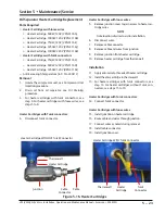
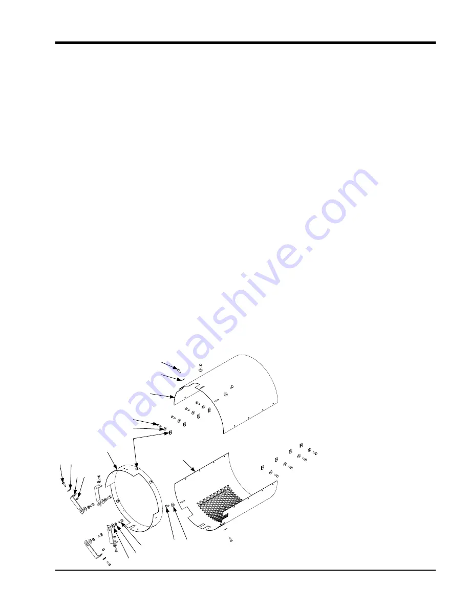
6.
Remove four nuts (4), screws (1) and flat
washers (2) securing ring mounting guard (5) to
four support brackets (3). Remove ring mounting
guard.
7.
Remove five fasteners (6) from ring mounting
guard (5).
8.
Remove four screws (9), lock washers (10) and flat
washers (11) securing support brackets (3) from
compressor. Remove support brackets. Discard
lock washers.
Installation
9.
Install four flat washers (11), new lock washers (10)
and screws (9) to secure support brackets (3) to
compressor. Do not fully tighten.
10.
Install five fasteners (6) to ring mounting guard (5).
11.
Install four screws (1), flat washers (2) and nuts (4)
to secure ring mounting guard (5) to four support
brackets (3).
12. Tighten nuts (4) and screws (9).
13. Install eight fasteners (6) to lower guard (8).
14.
Install two flat washers (2) and screws (1) to secure
lower guard (8) to ring mounting guard (5).
15.
Install three flat washers (2) and screws (1) to se
-
cure upper guard (7) to ring mounting guard (5).
16.
Install eight flat washers (2) and screws (1) to se
-
cure upper guard (7) to lower guard (8).
17. Return compressor unit to service.
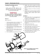
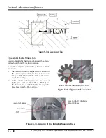
Coupling Guard Replacement
NOTE
Coupling guards may differ slightly but this
replacement procedure can be used to remove and
install them. The coupling guard assembly described
in this procedure is VPN A27435C.
WARNING
The design, construction, mounting and opening
of coupling guards should be performed following
proper local codes. Failure to comply may result in
serious injury or death.
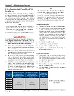
Removal
Reference Figure 5-19.
1. Shut down compressor unit, see Compressor Unit
Isolation for Maintenance/Service procedure.
2.
Remove eight screws (1) and flat washers (2) secur
-
ing upper guard (7) to lower guard (8).
3.
Remove three screws (1) and flat washers (2) se
-
curing upper guard (7) to ring mounting guard (5).
Remove upper guard.
4.
Remove two screws (1) and flat washers (2) secur
-
ing lower guard (8) to ring mounting guard (5).
Remove lower guard.
5. Remove eight fasteners (6) from lower guard (8).
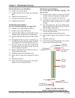
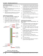
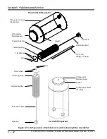
Figure 5-19. Coupling Guard Assembly
(VPN A27435C shown)
1 2
3 4
5
6
2
1
7
2
1
8
2
1
9
10
11
Summary of Contents for Vilter VSH
Page 2: ......
Page 30: ...2 4 Blank VSS VSM VSH VSSH Installation Operation and Maintenance Manual Emerson 35391SD ...
Page 54: ...3 24 Blank VSS VSM VSH VSSH Installation Operation and Maintenance Manual Emerson 35391SD ...
Page 74: ...4 20 Blank VSS VSM VSH VSSH Installation Operation and Maintenance Manual Emerson 35391SD ...
Page 144: ...5 70 Blank VSS VSM VSH VSSH Installation Operation and Maintenance Manual Emerson 35391SD ...
Page 156: ...7 4 Blank VSS VSM VSH VSSH Installation Operation and Maintenance Manual Emerson 35391SD ...
Page 158: ...8 2 Blank VSS VSM VSH VSSH Installation Operation and Maintenance Manual Emerson 35391SD ...
Page 204: ...8 48 Blank VSS VSM VSH VSSH Installation Operation and Maintenance Manual Emerson 35391SD ...
Page 206: ...A 2 Blank VSS VSM VSH VSSH Installation Operation and Maintenance Manual Emerson 35391SD ...
Page 210: ...B 4 Blank VSS VSM VSH VSSH Installation Operation and Maintenance Manual Emerson 35391SD ...
Page 216: ...C 6 Blank VSS VSM VSH VSSH Installation Operation and Maintenance Manual Emerson 35391SD ...
Page 219: ......
Page 221: ......
Page 224: ......
Page 225: ......
Page 226: ......
Page 242: ...E 12 Blank VSS VSM VSH VSSH Installation Operation and Maintenance Manual Emerson 35391SD ...
Page 248: ...G 2 Blank VSS VSM VSH VSSH Installation Operation and Maintenance Manual Emerson 35391SD ...
Page 249: ......