


5 – 31
Section 5 • Maintenance/Service
VSS/VSM/VSH/VSSH • Installation, Operation and Maintenance Manual • Emerson • 35391SD
18. Remove shims and spherical washers from com-
pressor mounting locations.
19. Inspect shims and spherical washers for damage,
replace as required.
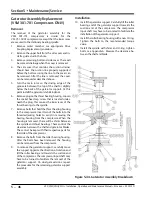
Installation
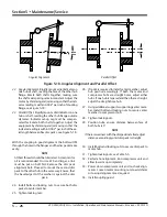
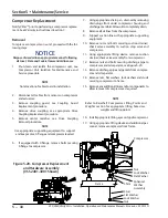
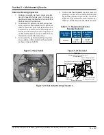
20. Install shims and spherical washers on compressor
mounting locations, see Figure 5-20.
21. Install appropriate lifting eyes on top of compressor.
22. Using appropriate lifting device, position compres-
sor on compressor mounting locations on frame.
23.
Loosely install studs, lock washers, flat washers and
nuts to secure compressor to frame until alignment
is correct.
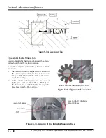
24. Check compressor for soft foot. Add or remove
shims as required until measurements are within
+/- 0.002”.
25. Tighten nuts to secure compressor to frame, refer
to Appendix A.
26.
If equipped with C-flange, install bolts to se
-
cure C-flange to compressor. Tighten bolts, see
Appendix A.
27. Install drive coupling, see appropriate Drive
Coupling Replacement procedure.
28. Install center member, see Drive Center Member
Installation and Alignment procedure.
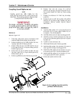
29. Install coupling guard, see Coupling Guard
Replacement procedure.
30. Install nuts and bolts to secure discharge pipe to oil
separator and compressor.
31. Tighten nuts on ‘discharge pipe-to-compressor
flange’ first, then tighten nuts on ‘discharge pipe-
to-oil separator flange’, see Appendix A.
32. Install nuts to secure suction strainer/check valve
assembly to compressor and suction stop valve.
33. Tighten nuts on ‘suction strainer/check valve as-
sembly-to-compressor’ first, then tighten nuts on
‘suction strainer/check valve assembly-to-suction
stop valve’, refer to Appendix A.
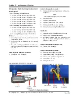
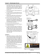
34. Install all lines to compressor.
35. Install all cables to sensors on compressor and
actuator.
36.
Perform leak check, see Compressor Unit Leak
Check procedure.
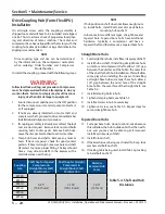
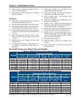
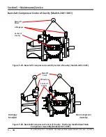
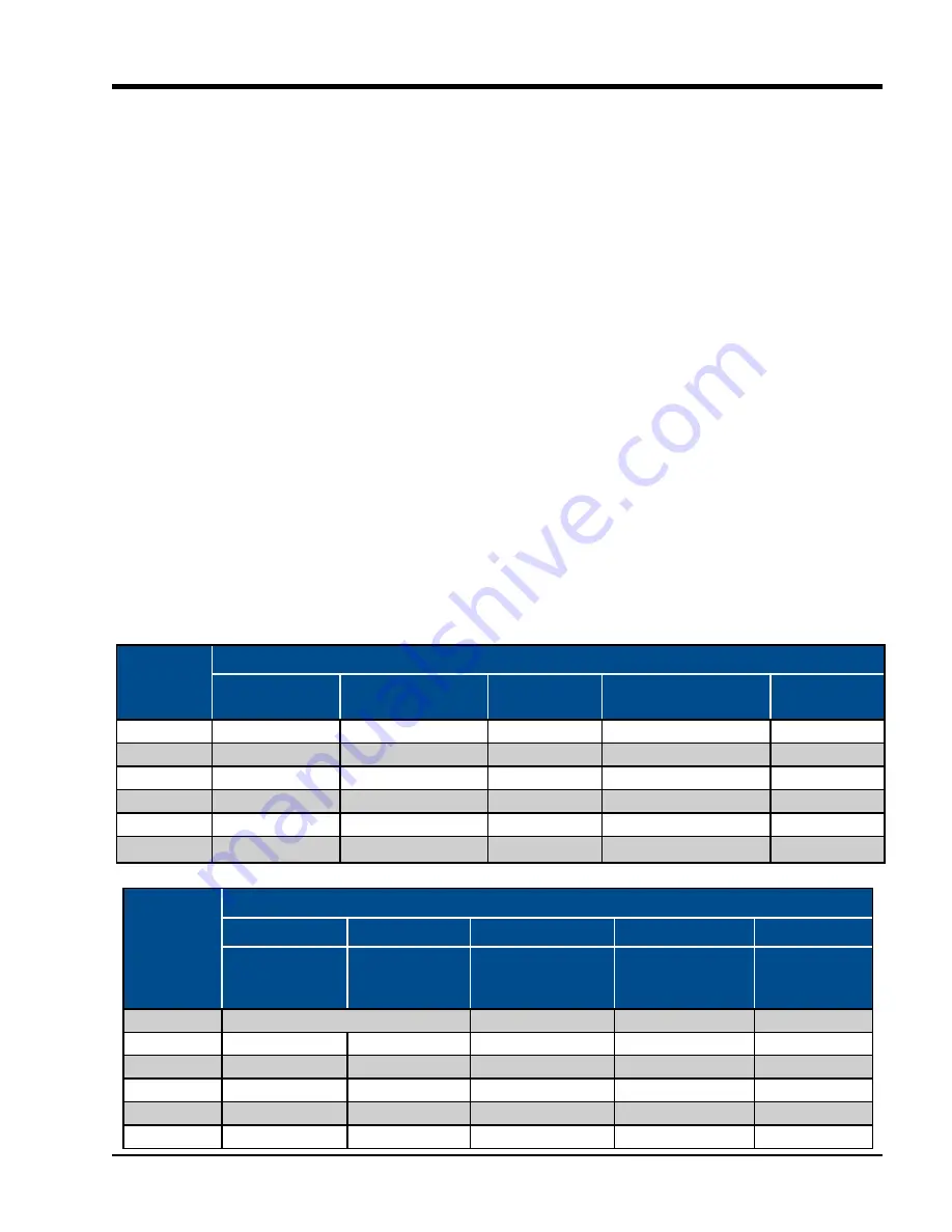
Bareshaft Compressor Lifting Points and Weights
Models
Component Weights
Gaterotor
Bearing Housing
Gaterotor Bearing
Housing Cover
Discharge
Manifold
Main Compressor
Assembly ONLY
Gaterotor
Cover
97-127
3.3 lbs (1.6 kg)
8 lbs (4 kg)
N/A
249 lbs (113 kg)
10 lbs (5 kg)
291-601
19 lbs (9 kg)
11 lbs (5 kg)
125 lbs (57 kg)
1105 lbs (502 kg)
46 lbs (21 kg)
751-901
28 lbs (13 kg)
11 lbs (5 kg)
177 lbs (80 kg)
1450 lbs (658 kg)
33 lbs (15 kg)
1051-1301
37 lbs (17 kg)
13 lbs (6 kg)
274 lbs (125 kg)
2006 lbs (910 kg)
42 lbs (19 kg)
1551-2101
54 lbs (24 kg)
19 lbs (9 kg)
349 lbs (158 kg)
3151 lbs (1429 kg)
70 lbs (32 kg)
2401-3001
58 lbs (27 kg)
32 lbs (15 kg)
788 lbs (358 kg)
4152 lbs (1883 kg)
150 lbs (68 kg)
Table 5-8. Bareshaft Compressor Component Weights
Models
Component Lifting Hole Sizes
A
B
C
D
E
Discharge
Manifold (Side)
Discharge
Manifold (Top)
Main Compressor
Assembly ONLY
(Discharge)
Main Compressor
Assembly ONLY
(Suction)
Gaterotor
Cover
97-127
A & B Lifting Points: 1/2 - 13 UNC -2B
-
-
-
291-601
5/8-11 UNC -2B
5/8-11 UNC -2B
5/8-11 UNC -2B
5/8-11 UNC -2B
3/8-16 UNC-2B
751-901
5/8-11 UNC -2B
5/8-11 UNC -2B
5/8-11 UNC -2B
5/8-11 UNC -2B
-
1051-1301
5/8-11 UNC-2B
5/8-11 UNC -2B
3/4-10 UNC -2B
5/8-11 UNC -2B
3/8-16 UNC -2B
1551-2101
5/8-11 UNC -2B
5/8-11 UNC -2B
5/8-11 UNC -2B
5/8-11 UNC -2B
3/8-16 UNC -2B
2401-3001
5/8-11 UNC -2B
5/8-11 UNC -2B
5/8-11 UNC -2B
3/4-10 UNC -2B
5/8-11 UNC -2B
Table 5-9. Bareshaft Compressor Component Lifting Hole Sizes
Summary of Contents for Vilter VSH
Page 2: ......
Page 30: ...2 4 Blank VSS VSM VSH VSSH Installation Operation and Maintenance Manual Emerson 35391SD ...
Page 54: ...3 24 Blank VSS VSM VSH VSSH Installation Operation and Maintenance Manual Emerson 35391SD ...
Page 74: ...4 20 Blank VSS VSM VSH VSSH Installation Operation and Maintenance Manual Emerson 35391SD ...
Page 144: ...5 70 Blank VSS VSM VSH VSSH Installation Operation and Maintenance Manual Emerson 35391SD ...
Page 156: ...7 4 Blank VSS VSM VSH VSSH Installation Operation and Maintenance Manual Emerson 35391SD ...
Page 158: ...8 2 Blank VSS VSM VSH VSSH Installation Operation and Maintenance Manual Emerson 35391SD ...
Page 204: ...8 48 Blank VSS VSM VSH VSSH Installation Operation and Maintenance Manual Emerson 35391SD ...
Page 206: ...A 2 Blank VSS VSM VSH VSSH Installation Operation and Maintenance Manual Emerson 35391SD ...
Page 210: ...B 4 Blank VSS VSM VSH VSSH Installation Operation and Maintenance Manual Emerson 35391SD ...
Page 216: ...C 6 Blank VSS VSM VSH VSSH Installation Operation and Maintenance Manual Emerson 35391SD ...
Page 219: ......
Page 221: ......
Page 224: ......
Page 225: ......
Page 226: ......
Page 242: ...E 12 Blank VSS VSM VSH VSSH Installation Operation and Maintenance Manual Emerson 35391SD ...
Page 248: ...G 2 Blank VSS VSM VSH VSSH Installation Operation and Maintenance Manual Emerson 35391SD ...
Page 249: ......