156
Unidrive M702 User Guide
Issue Number: 3
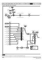
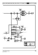
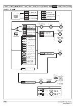
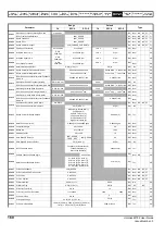
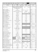
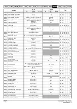
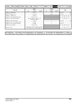
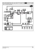
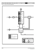
Figure 11-5 P1 Interface
15 way sub-D
connector
03.050
P1 Feedback Lock
03.044
P1 Reference
Scaling
??.???
Any
unprotected
variable
parameter
??.???
03.046
P1 Reference
Destination
03.056
P1 Feedback Reverse
03.036
P1 Supply Voltage
03.066
P1 Resolver Excitation
03.038
P1 Device Type
P1 Termination Select
03.039
03.040
P1 Error Detection Level
P1 Additional
Power-Up Delay
03.049
03.051
0
1
P1 Linear
Feeback Select
03.033
P1 Rotary Turns Bits
03.034
P1 Rotary Lines
Per Revolution
03.052
P1 Linear Comms Bits
03.053
P1 Linear Line Pitch
03.055
P1 Pole Pitch
P1 Revolution /
Pole Pitch Counter
03.028
03.029
P1 Position
03.030
P1 Fine
Position
03.031
P1 Marker Mode
03.032
P1 Marker Flag
03.057
P1 Normalization Turns
03.058
P1 Normalized
Position
03.059
P1 Normalized
Marker Position
03.037
P1 Comms Baud Rate
03.041
P1 Auto-Configuration
Enable
03.047
P1 SSI Incremental
Mode
03.035
P1 Comms Bits
03.048
P1 SSI Binary Mode
03.060
P1 Calculation Time
03.061
P1 Recovery Time
03.062
P1 Line Delay Time
P1 Low Speed Update
Rate Active
03.064
P1 Encoder Protocol
Detected
03.067
P1 User Comms Enable
03.068
P1 User Comms
Transmit Register
03.069
P1 User Comms
Receive Register
03.063
03.042
P1 Feedback Filter
03.027
P1 Speed
Feedback
03.065
03.065
03.043
P1 Maximum Reference
03.045
P1
Reference
P1 Resolver Poles
mm.ppp
mm.ppp
Key
Read-write (RW)
parameter
Read-only (RO)
parameter
Input
terminals
Output
terminals
X
X
X
X
The parameters are all shown in their default settings
Summary of Contents for Unidrive M702
Page 283: ......
Page 284: ...0478 0002 03 ...


