


Instruction Manual
D103785X012
Calibration
June 2017
48
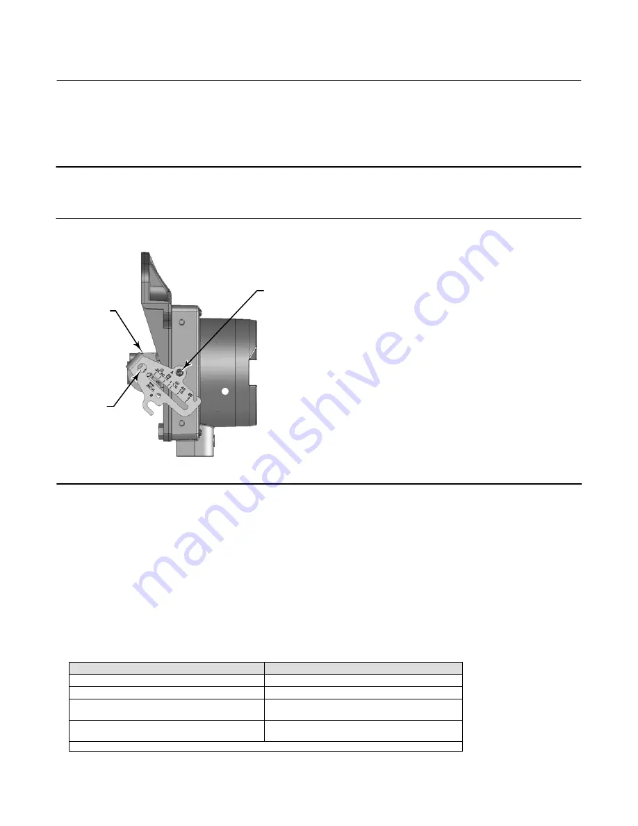
2. As shown in figure 4‐2, align the feedback arm (key 79) with the housing by inserting the alignment pin (key 46)
through the hole marked “A” on the feedback arm. Fully engage the alignment pin into the tapped hole in the
housing.
Note
The alignment pin (key 46) is stored inside the remote feedback unit housing.
Figure 4‐2. FIELDVUE DVC6015 Remote Feedback Unit Showing Feedback Arm in Position for Travel Sensor
Adjustment
FEEDBACK ARM
(KEY 79)
B
TRAVEL
SENSOR
SHAFT
ALIGNMENT PIN
(KEY 46)
X0918
3. Loosen the screw that secures the feedback arm to the travel sensor shaft. Position the feedback arm so that the
surface of the feedback arm is flush with the end of the travel sensor shaft.
4. Connect a current source to the instrument LOOP - and LOOP + terminals. Set the current source to any value
between 4 and 20 mA. Connect the Field Communicator to the TALK terminals.
5. Before beginning the travel sensor adjustment, set the instrument mode to Out Of Service and the protection to
None.
6. From the
Calibrate
menu select
Sensor Calibration, Travel Sensor.
Follow the prompts on the Field Communicator
display to adjust the travel sensor counts to the value listed in table 4‐2.
Table 4‐2. Travel Sensor Counts
Remote Feedback Unit
Travel Sensor Counts
DVC6015
700
±
200
DVC6025
2100
±
200
DVC6035
Counterclockwise shaft rotation
600
±
200
DVC6035
Clockwise shaft rotation
3400
±
200
1. Refer to figure 4‐3 to determine the desired starting position for the DVC6035 based on potentiometer shaft; counterclockwise or clockwise.


