


Instruction Manual
D200156X012
4194HA, HB, HC Controllers
July 2018
41
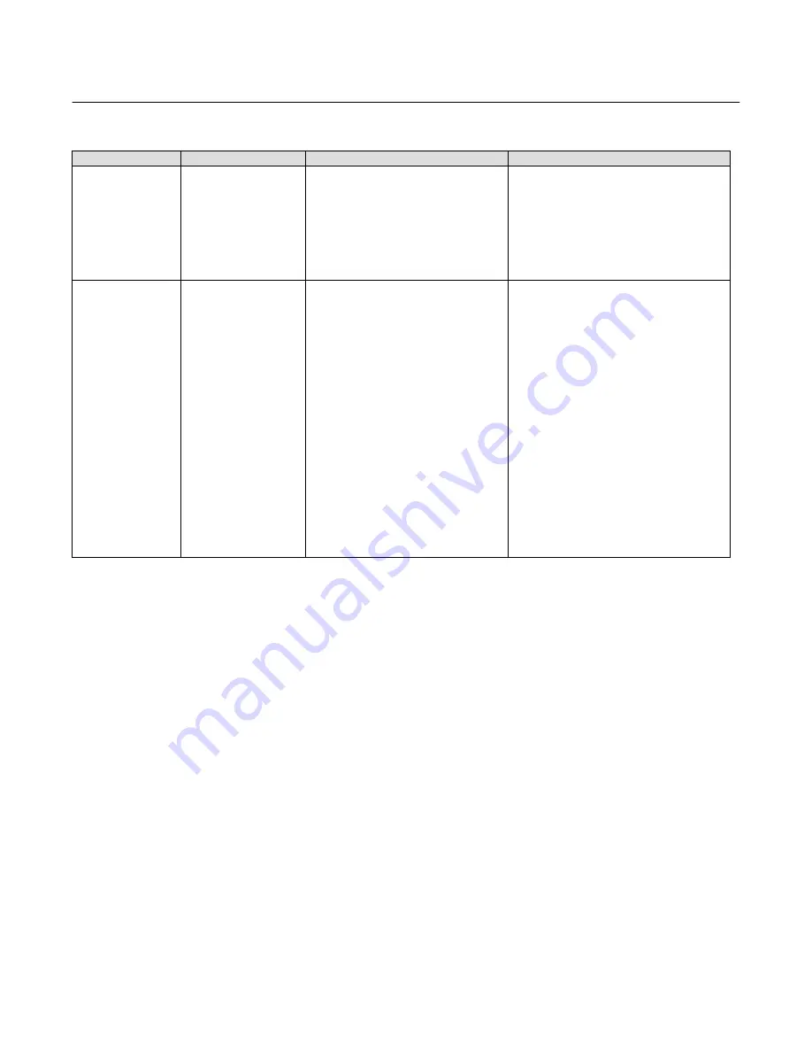
Table 5‐1. Troubleshooting Chart (Continued)
Correction
Check
Possible Cause
Fault
7. Controller remains
at full output.
(continued)
7.5 Relay failure or
restriction in nozzle
passage.
7.5 Manually move flapper 1.6 mm
(1/16‐inch) from the nozzle.
7.5 If the output pressure remains at the supply
pressure, remove the controller case and cover
assembly and test again with the relay nozzle
tubing nut loose. If the output is 0 bar (0 psig),
clean or replace the nozzle assembly. If the
output remains at supply pressure, replace the
relay.
7.6 Flapper misaligned.
7.6 Manually push the flapper away from the
nozzle. Controller output should go to 0 psig.
7.6 Perform the flapper alignment procedure.
8. Controller remains
at zero output.
8.1 Gauge not
functioning.
8.1 Verify that the supply pressure is at its
correct value and that the controller output
is zero.
8.1 Replace gauges as necessary.
8.2 Differential pressure
unit or linkage failure.
8.2 Vary the process differential pressure and
observe the flapper. Inspect the sensor and
linkages for damage. Refer to the differential
pressure unit instruction manual.
8.2 Repair or replace parts as necessary.
8.3 Mechanical alignment.
8.3 Move the set point and verify that the
nozzle can be capped by the flapper. If not,
inspect linkages and flexures for damage.
8.3 Repair or replace parts as necessary.
8.4 Relay malfunction.
8.4 With the supply pressure on, check for a
low flow of air at the nozzle output. When
capped, the output pressure should build
rapidly. The relay should open and pass a
large flow of air through the “OUTPUT”
nipple.
8.4 Press the cleanout wire on the relay. If the
problem persists, replace the relay.
8.5 Nozzle pressure leak.
8.5 Check for nozzle tubing leaks with a soap
solution with the nozzle capped by the
flapper. Press on the nozzle cap gently to
ensure the nozzle O‐ring is sealing. Ensure
the relay nozzle tubing nut is tight and the
manifold screws (keys 34 and 131) are tight.
8.5 Tighten the relay nozzle tubing nut, tighten
manifold screws (keys 34 and 131), or replace
nozzle assembly O‐ring or set point beam
assembly as appropriate.
Changing Controller Action
The following steps describe changing controller action from direct (increasing process differential pressure produces
increasing output pressure) to reverse (increasing process differential pressure produces decreasing output pressure)
or vice versa.
1. Loosen two screws (key 6) in the proportional band indicator cover (key 36). Do not remove the screws.
2. Lift the proportional band indicator cover as shown in figure 5‐2.
3. Rotate the proportional band knob (key 25) to the desired controller action.
4. Install the proportional band indicator cover (key 36) and tighten the two screws (key 6).


