


Product data sheet
FieldQ
FieldQ
Copyright © Emerson. The information in this document is subject to change without notice. Updated data sheets can be obtained from our website
www.emerson.com/fieldq or from your Emerson Automation Solutions - Actuation Technologies Center:
America’s:
+1 281 477 4100
Europe:
+36 22 53 0950
Asia/Pacific:
+65 67 77 8211
1.606.06 Rev. 0 page 3 of 3
October 2017
Position feedback using the control modules
Important:
Caution:
Screwing in only one adjustment screw or un-equal setting of
both the screws can lead to premature failure of the actuator.
7. Test cycle the actuator to check if the correct rotation angle is
set. If required, repeat steps 3 to 6 to adjust the rotation angle
to the required angle.
Actuator angle rotation per full revolution of screw
Actuator
size
Stroke
Screw
Actuator angle rota-
tion per full revolution
of screw
mm
inch
Thread
Pitch
(mm)
40
18.8
0.74
M8
1.25
6.0°
65
22.0
0.87
M8
1.25
5.1°
100
25.1
0.99
M10
1.5
5.4°
150
31.4
1.24
M10
1.5
4.3°
200
37.7
1.48
M10
1.5
3.6°
350
37.7
1.48
M12
1.75
4.2°
600
44.0
1.73
M16
2
4.1°
950
50.3
1.98
M16
2
3.6°
1600
62.8
2.47
M20
2.5
3.6°
15°
max
15°
max
Open
Closed
For control modules QC40,
QC41, QC42 and QC43:
- The switch points cannot
be set throughout the full
stroke but is limited to maxi-
mum 15°.
- If the closed position is at 0°,
then the module will send
a closed signal as position
feedback.
- Control Module QC54
(Foundation Fieldbus) does allow switch point setting
throughout the stroke.
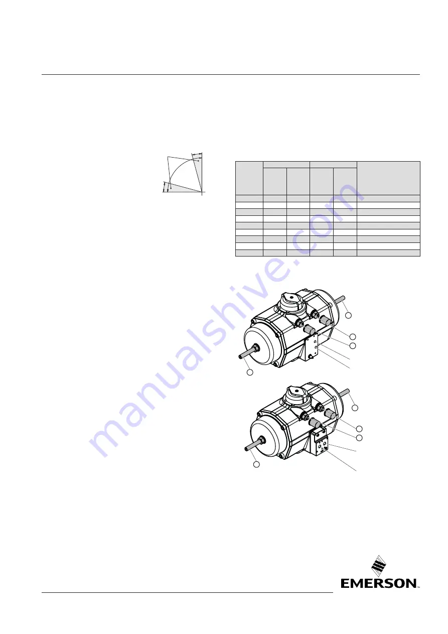
Full Stroke Adjustment setting:
1. Starting point:
- The Full Stroke Adjustment actuators are shipped by default
with a rotation of 90° +/-0.5° (See page 1)
- For easy applying pressure during this setting procedure it is
recommended to remove the control module. The NAMUR
adaptation plate can stay on the actuator.
2. In order to set the Full Stroke Adjustment Screws accurately to
the outward position:
- Do not change the limit stop screws (2) and (3) located
above the air connection interface.
- Move the pistons of the actuator outwards by applying
pressure to the A-port.
3. Screw in both the Full Stroke Adjustment Screws (1) until the
screw touches the pistons. You will feel an obstruction.
Important:
Do not overtighten the screws.
You have now set the adjustment screw to the outward (90°)
position.
4. Move the pistons of the actuator inwards.
- For Spring Return actuator is happens automatically when
the actuator is vented.
- For double acting actuators vent the A-port and apply pres-
sure to the B-port.
5. In order to set the actuator to the required angle, use next
table to define the number of revolutions which you have to
turn in the Full Stroke Adjustment Screws.
6. Turn in both the adjustment screws as defined in step 5. Both
the adjustment screws should be turned in with the same
length or number of revolutions.
2
3
1
2
3
1
1
1
A - Port (1/8” BSP)
B - Port (1/8” BSP)
A - Port
(1/4” NPT or BSP)
B - Port
(1/4” NPT or BSP)


