Safet
Introducti
Inst
Pow
Pro Sof
C
How
How
C
S
S
Parame
Drive
D
G
Ind
e
EZMotion User/Programming Guide
75
Revision A8
www.controltechniques.com
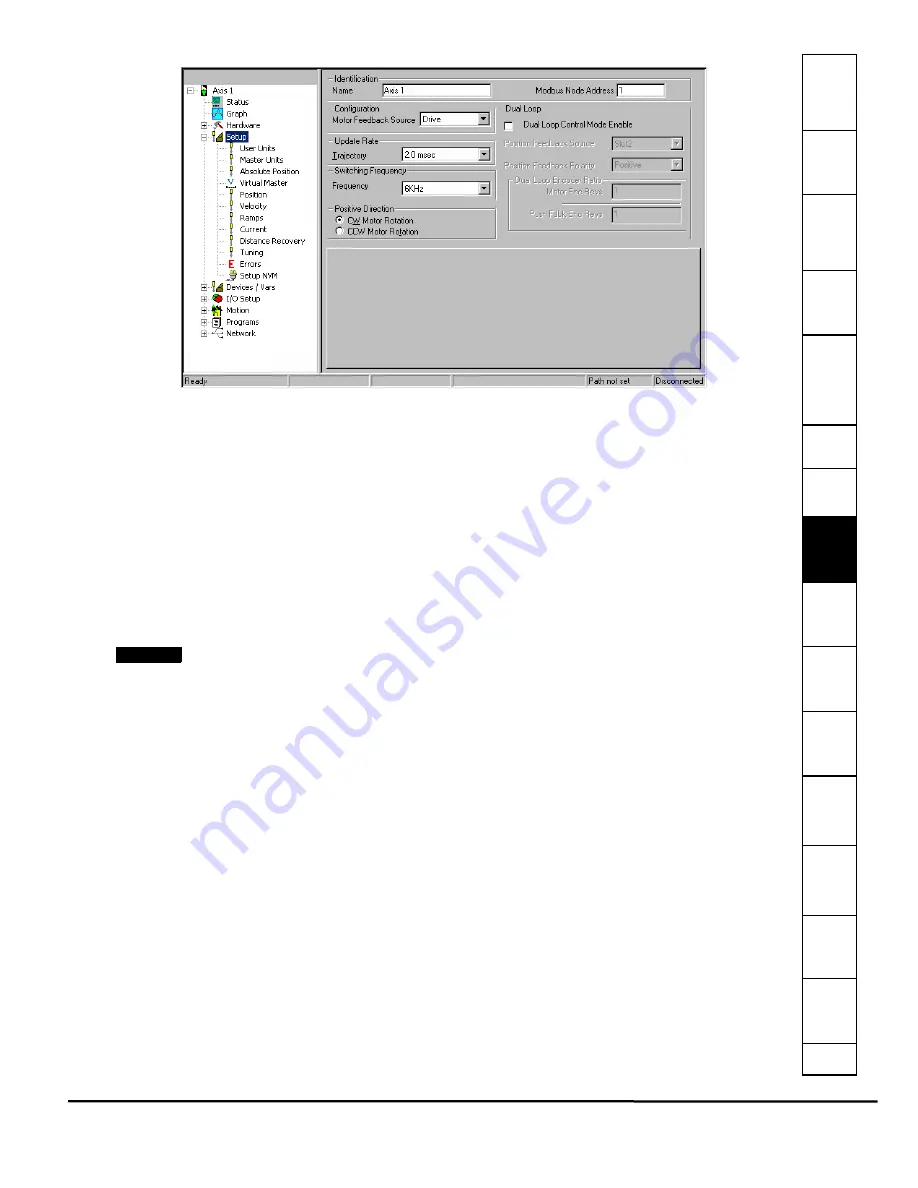
Figure 80:
Setup View
Identification Parameters
Name
This is a 12-character alpha/numeric user-configured name for this axis. Enter the name for the device you are currently
setting up. Assigning a unique name for each device in your system allows you to quickly identify a device when downloading,
editing, and troubleshooting. All keyboard characters are valid. This will default to Axis 1.
Modbus Node Address
This is the Modbus address of the target drive to which you will download the configuration. The default target drive address is
1.
Configuration
Motor Feedback Source
Motor Feedback Source allows the user to specify where the motor feedback device is connected to the Unidrive SP/Digitax
ST. Early releases of PowerTools Pro and EZMotion only allow selection of "Drive".
NOTE
When the Dual Loop Mode feature is used, this specifies the location of connection for the motor feedback device even
though a different feedback device is being used to close the position loop.
Update
Trajectory Update
This parameter configures the interrupt interval for the processor. This defines how often the motion program is interrupted
and the Control Loop is processed. In the Control Loop, the feedback information is processed and a new position command
is generated. Also in the Control Loop, the I/O is scanned.
Available selections for Trajectory Update Rate are 1, 1.25, 1.5, 1.75, 2, 2.25 and 2.5 milliseconds. The longer the update rate,
the more time is dedicated to the user programs, and the less time dedicated to servo performance. The shorter the update
rate, the more precise the servo performance, but less time is available to process user programs. Diagnostics are available
on the Status Online tab when online with the device to help select the ideal setting. (See description of Control Loop Group of
online parameters for further information).
Switching Frequency
Frequency
This parameter defines the switching frequency of the Unidrive SP/Digitax ST. Available switching frequencies are 3kHz,
4kHz, 6kHz, 8kHz, 12kHz and 16kHz. For more information on how the switching frequency effects drive performance refer to
the Unidrive SP
User Guide
or the
Digitax ST
User Guide.
Positive Direction
The Positive Direction consists of a CW (clockwise) Motor Rotation Radio Button or a CCW (counter-clockwise) Motor
Rotation Radio Button.
The motion will move in either CW direction or CCW direction. Perspective of rotation is defined as you face the motor shaft
from the front of the motor.
CW Motor Rotation Radio Button
Select this radio button for applications in which CW motor rotation is considered to be motion in the positive direction
Summary of Contents for EZMotion
Page 2: ......
Page 12: ...x EZMotion User Programming Guide www controltechniques com Revision A8 ...
Page 18: ...6 EZMotion User Programming Guide www controltechniques com Revision A8 ...
Page 36: ...24 EZMotion User Programming Guide www controltechniques com Revision A8 ...
Page 158: ...146 EZMotion User Programming Guide www controltechniques com Revision A8 ...
Page 186: ...174 EZMotion User Programming Guide www controltechniques com Revision A8 ...
Page 266: ...256 EZMotion User Programming Guide www controltechniques com Revision A8 ...
Page 267: ......


