20 • PerformanceAlert Gateway I&O Manual
8
E2 Applications
The PerformanceAlert™ Gateway provides a means
for E2 to use data from the PerformanceAlert™ modules
for general logging, alarming, and control purposes. For
convenience, this section will cover some of the most com-
mon and useful applications of PerformanceAlert™ data in
E2 applications.
8.1.
Passing Perfor-
manceAlert™ Alarm Data to
the E2 Advisory Log
The E2 features many advanced alarm control capabil-
ities, all of which are centered around the collection of
alarms kept in the E2 Advisory Log. Though the Perfor-
manceAlert™ Gateway passes alarm information from
PerformanceAlert™ modules to the E2, it only does so as
I/O point data, not as alarms written to the E2 Advisory
Log.
In order to write PerformanceAlert™ alarm data to the
E2 Advisory Log, you must set up Generic Alarming pa-
rameters on the Gateway’s virtual I/O points.
8.1.1. Generic Alarming Setup
Setting up Generic Alarming for PerformanceAlert™
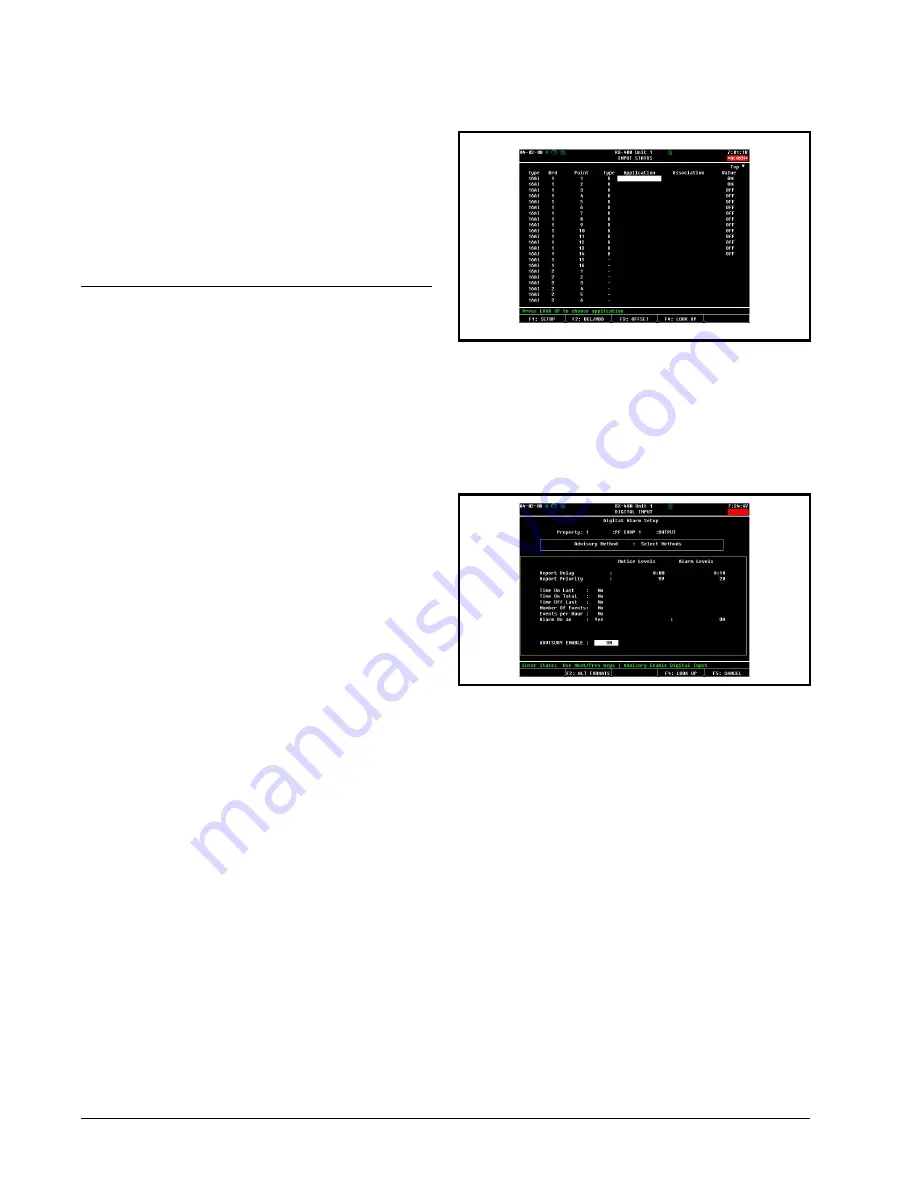
Gateway I/O points is done from the E2 Input Status
Screen.
1. Log in to the E2 and press
I
(Input
Definitions).
2. If you have not yet done point setup for the
Gateway’s virtual I/O points, follow the steps
outlined in
. When point setup is com-
plete for all PerformanceAlert™ Gateway
virtual I/O points, you should see the letter
"D" next to each PerformanceAlert™ input
point. In the example
, the Gate-
way is operating in Condensed Mode desig-
nated as 16AI board #1, with all fourteen I/O
points set up:
3. Highlight the point you want to set up. Press
A
: SETUP. The Digital Input or Analog
Input screen will be displayed.
4. Press
A
: SET ALARMS. The Digital
Alarm Setup or Analog Alarm Setup screen
will appear.
After completing Step 4, complete generic alarm setup
by following the instructions appropriate for the input type
(Digital or Analog).
8.1.2. Alarm Parameter Settings
8.1.2.1. Digital Alarms
For all Condensed Mode data points, and for all Ex-
panded Mode data points except 13, 14, and 15, digital
alarming may be set up so that an alarm will be generated
when the point transitions to the ON state.
Continuing from step 4 of
5. Set the Advisory Method field to "Select
Methods."
6. In the "Alarm On an" field, set this field to
"Yes" and press
>
. A field will appear to
the right of the cursor where you may choose
which digital state will trigger the alarm. Set
this field to ON.
Figure 8-1
- Input Status Screen (Condensed Mode Shown)
Figure 8-2
- Digital Alarm Setup Screen


