Passing PerformanceAlert™ Alarm Data to the E2 Advisory Log
E2 Applications • 21
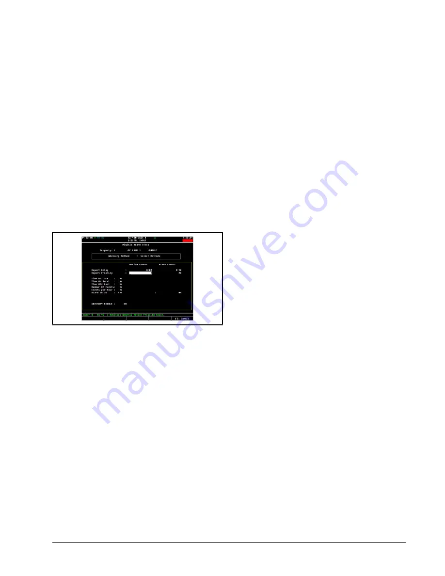
7. In the Report Delay and Report Priority
Fields, you must decide three things: whether
you want a PerformanceAlert™ advisory to
be an ALARM or NOTICE in the E2 Adviso-
ry log; what report priority you want the
alarm to be; and how long the Perfor-
manceAlert™ alarm must be active before
the alarm will be generated.
In the example shown in
, the ad-
visoryis configured to be an ALARM gener-
ated after a ten minute delay with a report
priority of 20. You will generally want to set
up critical alarms such as Locked Rotor or
Phase Fail as ALARM advisories with a pri-
ority of 20 or above. To keep a point from
generating notices, the Report Priority under
the Notice column is set to 0
To make an advisory appear as a low-priority
notice, enter a 99 in the Report Priority "No-
tice Levels" column and a 0 in the Report Pri-
ority "Alarm Levels" column.
8. Press
J
to save changes and return to the
Digital Input Setup screen. Note the OUT-
PUT fields at the bottom of the screen now
has the additional letter "A" at the end. This
signifies that this point has active generic
alarming parameters.
9. Press
J
to return to the Input Status
screen. Repeat steps 1 through 8 for the re-
maining digital PerformanceAlert™ Gate-
way points until all digital points are set up
for alarming.
8.1.2.2. Analog Alarms
The only analog values on the PerformanceAlert™
Gateway are points 13, 14, and 15 of each virtual 16AI
board that represents a PerformanceAlert™ module when
the Gateway is operating in Expanded Mode. Points 13 and
14 are current values; point 15 is the discharge line temper-
ature.
Of these analog points, it is not necessary to set up ge-
neric alarming on points 13 and 14. On point 15, the dis-
charge line temperature, alarming already occurs with high
discharge causes a trip condition to occur (in Expanded
Mode, Generic Alarming should be set up for this condition
on point 1). If desired, you may use Generic Alarming to
generate a warning when discharge line temperature runs
too close to the trip setpoint.
Continuing from step 4 of
5. Set the Advisory Method field to "Absolute
Levels."
6. Set the Advisory Use field to "Instanta-
neous."
7. In the "Notice Levels" column, highlight the
"Occupied Hi" field, and enter the desired
warning temperature threshold. This value
should not be higher than the programmed
DLT trip setpoint in the PerformanceAlert™.
8. In the "Notice Levels" column, set the Report
Delay to the desired amount of time (in
HH:MM) the discharge line temperature
must remain at or above the Occupied Hi
field value to cause the advisory to occur.
9. In the "Notice Levels" column, set the Report
Priority to 99 (the lowest possible priority
level).
10. In the "Notice Levels" column, highlight the
Return to Normal Delta field, and enter the
number of degrees the discharge line temper-
ature must fall below the value in the Occu-
pied Hi field to set the advisory status to
"return-to-normal."
11. In the "Alarm Levels" column, highlight the
Report Priority field and change its value to
zero to disable generation of ALARM advi-
sories.
Figure 8-3
- Digital Alarm Settings


