Using PerformanceAlert™ Current Transducer Values as Compressor Proofs
E2 Applications • 23
8.2.2.1. General
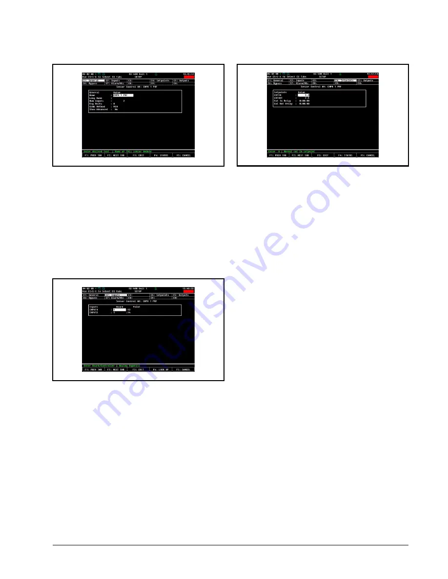
In the Name field, enter "CMP x PRF" (where x is the
address of the PerformanceAlert™ module whose current
transducer values will be using for proofing by this appli-
cation). Set all other values in this screen as shown in
Num Inputs
: 2
Eng Units
: A
Comb Method
: MIN
Show Advanced
: No
8.2.2.2. Inputs
In the Inputs tab, enter the board and point address of
the T1 and T3 currents from the PerformanceAlert™ Gate-
way in the Input1 and Input2 fields. The board number
should correspond to the address number of the Perfor-
manceAlert™ module. T1 will always be point #13 and T3
will always be point #14.
8.2.2.3. Setpoints
In the Setpoints tab, enter 3.0 in the CUTIN field and
2.5 in the CUTOUT field. These setpoints will result in the
sensor control output being ON when the current is above
3 amps and OFF whenever it falls below 2.5 amps. Leave
the Cut In Delay and Cut Out Delay fields set to 0:00:00.
8.2.3. Setting Up Proofing in Suction
Group Applications
After entering the CUTIN and CUTOUT setpoints in
the Setpoints tab (
), press ) to save changes
and exit. You are now ready to configure the compressor in
the suction group to use the output of the sensor control ap-
plication as its proof.
The instructions below assume the compressor rack is
already set up in a pre-existing Enhanced Suction group ap-
plication. Refer to the E2 User’s Guide for information on
setting up a suction group.
1. Press
I
(Configured Applications).
2. Press
to select "Suction Groups" from the
Configured Applications menu.
3. If more than one Suction Group application is
present, highlight the suction group the com-
pressor belongs to, and press
>
.
4. From the suction group’s Status Screen, press
Figure 8-6
- Analog Sensor Control Compressor Proofing -
General Screen
Figure 8-7
- Analog Sensor Control Compressor Proofing -
Inputs Screen
Figure 8-8
- Analog Sensor Control Compressor Proofing -
Setpoints Screen


